Nissan Pathfinder. Instruction - part 1141


  Index      Nissan     Nissan Pathfinder (2014 year) - Service and Repair Instruction


Search            copyright infringement  


Content   ..  1139  1140  1141  1142   ..


Nissan Pathfinder. Instruction - part 1141


STRUCTURE AND OPERATION

TM-23

< SYSTEM DESCRIPTION >

[CVT: RE0F10E]

C

E

F

G

H

I

J

K

L

M

A

B

TM

N

O

P

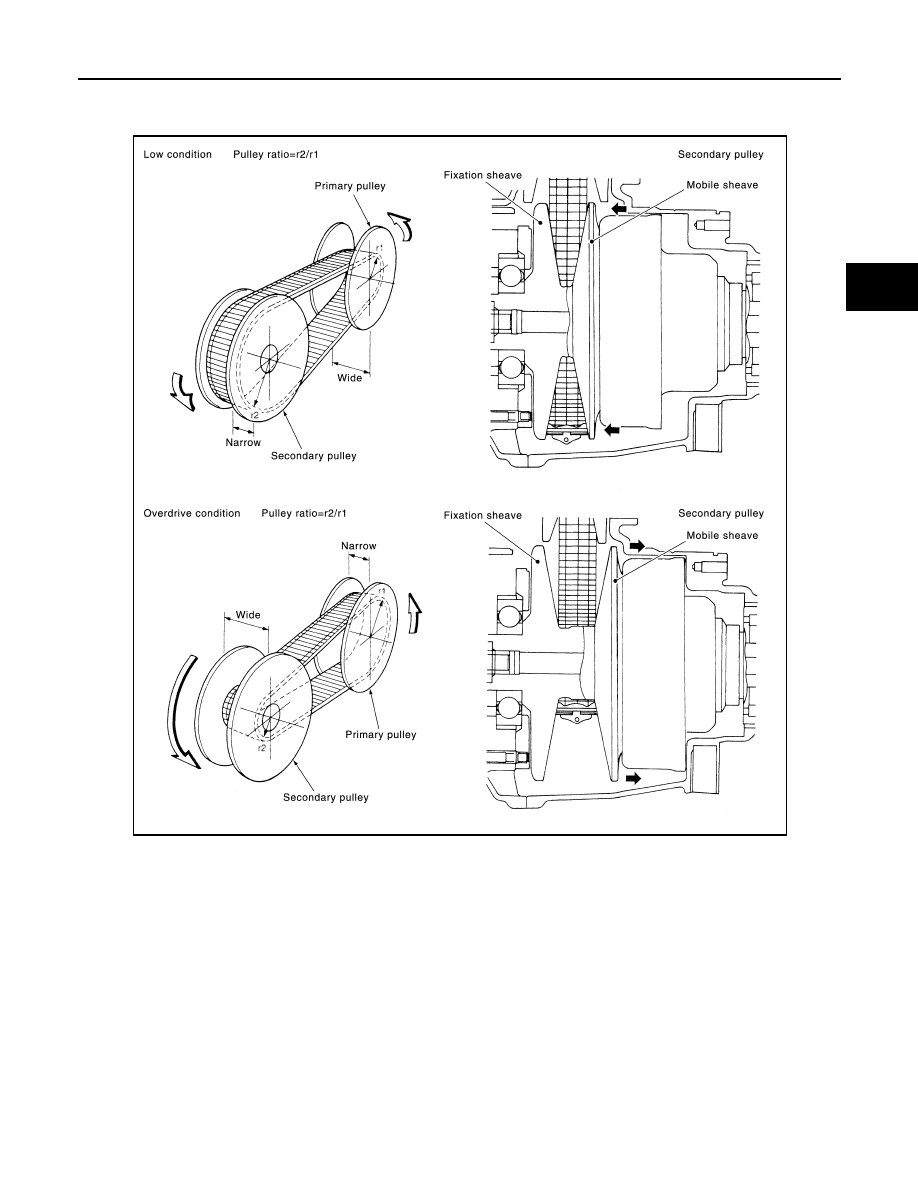
The movable sheave slides on the shaft to change the groove width of the pulley. Input signals of engine load

(accelerator pedal opening), primary pulley speed and secondary pulley speed change the operation pres-

sures of the primary pulley and the secondary pulley, and controls the pulley groove width. 

FINAL DRIVE AND DIFFERENTIAL

The deceleration gears are composed of 2 stages: primary deceleration (output gear, idler gear pair) and sec-

ondary deceleration (reduction gear, final gear pair). All of these gears are helical gears.

JSDIA2429GB

TM-24

< SYSTEM DESCRIPTION >

[CVT: RE0F10E]

STRUCTURE AND OPERATION

The lubrication oil is the same as the CVT fluid which lubricates the entire transaxle.

TRANSAXLE : Operation Status

INFOID:0000000009177502

×: Engaged or applied.

JSDIA2427GB

Selector lever 

position

Parking mech-

anism

Forward 

clutch

Reverse brake  Primary pulley 

Secondary 

pulley

Chain belt

Final drive

P

×

R

×

×

×

×

×

N

D, L

×

×

×

×

×

STRUCTURE AND OPERATION

TM-25

< SYSTEM DESCRIPTION >

[CVT: RE0F10E]

C

E

F

G

H

I

J

K

L

M

A

B

TM

N

O

P

TRANSAXLE : Oil Pressure System 

INFOID:0000000009177503

Oil pressure required for operation of the transaxle transmission mechanism is generated by oil pump, oil

pressure control valve, solenoid valve, etc. 

TRANSAXLE : Component Description

INFOID:0000000009177504

JSDIA3786GB

Part name

Function

Torque converter

Increases engine torque and transmits it to the transaxle.

Oil pump

Utilizes a vane-type oil pump that is driven by the engine through the oil pump drive chain in order to 
increase efficiency of pump discharge volume in low-speed zone and optimize pump discharge volume 
in high-speed zone. Discharged oil from oil pump is transmitted to control valve. It is used as the oil of 
primary and secondary pulley operation, the oil of clutch operation, and the lubricant for each part.

Forward clutch

The forward clutch is wet and multiple plate type clutch that consists of clutch drum, piston, drive plate, 
and driven plate. It is a clutch to move the vehicle forward by activating piston hydraulically, engaging 
plates, and directly connecting sun gear and input shaft.

Reverse brake

The reverse brake is a wet multiple-plate type brake that consists of transaxle case, piston, drive plate, 
and driven plate. It is a brake to move the vehicle in reverse by activating piston hydraulically, engaging 
plates, and fixing planetary gear.

Internal gear

The internal gear is directly connected to forward clutch drum. It is a gear that moves the outer edge of 
pinion planet of planet carrier. It transmits power to move the vehicle in reverse when the planet carrier 
is fixed.

Planet carrier

Composed of a carrier, pinion planet, and pinion shaft. This gear fixes and releases the planet carrier in 
order to switch between forward and reverse driving.

Sun gear

Sun gear is a set part with planet carrier and internal gear. It transmits transmitted force to primary fixed 
sheave. It rotates in forward or reverse direction according to activation of either forward clutch or re-
verse brake.

TM-26

< SYSTEM DESCRIPTION >

[CVT: RE0F10E]

STRUCTURE AND OPERATION

FLUID COOLER & FLUID WARMER SYSTEM
FLUID COOLER & FLUID WARMER SYSTEM : System Description

INFOID:0000000009177505

CVT FLUID COOLER SCHEMATIC

COMPONENT DESCRIPTION

CVT Oil Warmer

Input shaft

The input shaft is directly connected to forward clutch drum and transmits traction force from torque con-
verter. In shaft center, there are holes for hydraulic distribution to primary pulley and hydraulic distribution 
for lockup ON/OFF.

Primary pulley

It is composed of a pair of pulleys (the groove width is changed freely in the axial direction) and the chain 
belt. The groove width changes according to wrapping radius of steel belt and pulley from low status to 
overdrive status continuously with non-step. It is controlled with the oil pressures of primary pulley and 
secondary pulley.

Secondary pulley

Chain belt

Instruction shaft

When the instruction shaft is in the P position, the parking rod that is linked to the instruction shaft rotates the 
parking pole. When the parking pole rotates, it engages with the parking gear, fixing the parking gear. As 
a result, the secondary pulley that is integrated with the parking gear is fixed.

Parking rod

Parking pawl

Parking gear

Output gear

The deceleration gears are composed of 2 stages: primary deceleration (output gear, idler gear pair) and 
secondary deceleration (reduction gear, final gear pair). All of these gears are helical gears.

Idler gear

Reduction gear

Differential 

Torque converter regulator 
valve

Adjusts the feed pressure to the torque converter to the optimum pressure corresponding to the driving 
condition.

Pressure regulator valve

Adjusts the discharge pressure from the oil pump to the optimum pressure (line pressure) corresponding 
to the driving condition.

Torque converter clutch 
control valve

Adjusts the torque converter engage and disengage pressures.

Instruction valve

Distributes the clutch operation pressure to each circuit according to the selector lever position.

Secondary reducing valve

Reduces line pressure and adjusts secondary pressure.

Primary reducing valve

Reduces line pressure and adjusts primary pressure.

Pilot valve A

Reduces line pressure and adjusts pilot pressure to the solenoid valves listed below.
• Primary pressure solenoid valve
• Secondary pressure solenoid valve
• Select solenoid valve
• Line pressure solenoid valve

Pilot valve B

Reduces pilot pressure and adjusts pilot pressure to the torque converter clutch solenoid valve.

Part name

Function

JSDIA4090GB


Content   ..  1139  1140  1141  1142   ..