Nissan Pathfinder. Instruction - part 1059


  Index      Nissan     Nissan Pathfinder (2014 year) - Service and Repair Instruction


Search            copyright infringement  


Content   ..  1057  1058  1059  1060   ..


Nissan Pathfinder. Instruction - part 1059


B2198 NATS ANTENNA AMP.

SEC-99

< DTC/CIRCUIT DIAGNOSIS >

[WITH INTELLIGENT KEY SYSTEM]

C

D

E

F

G

H

I

J

L

M

A

B

SEC

N

O

P

Is the inspection result normal?

YES

>> GO TO 3.

NO

>> Repair or replace harness.

3.

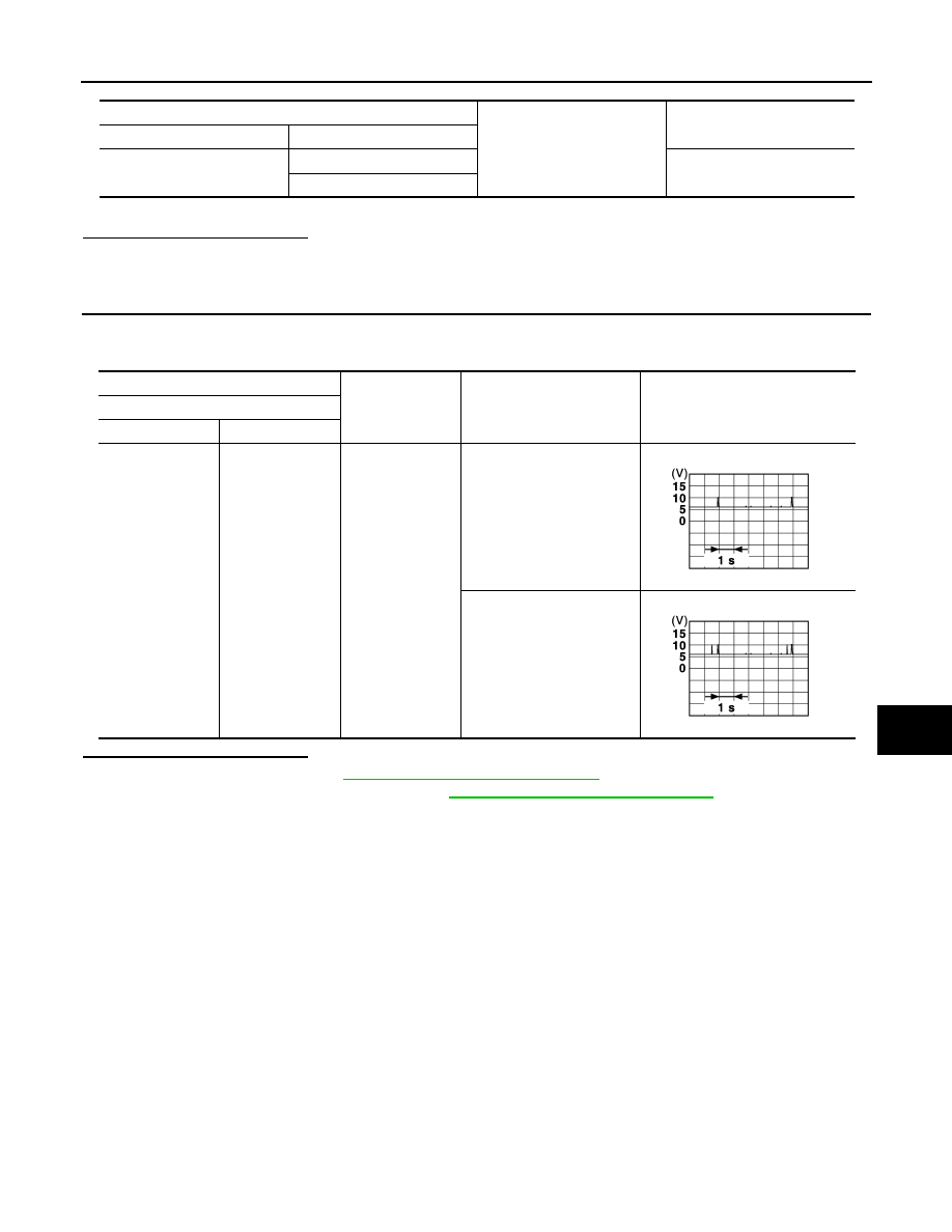
CHECK NATS ANTENNA AMP INPUT SIGNAL 1

1. Turn ignition switch ON.

2. Check signal between BCM harness connector and ground using oscilloscope.

Is the inspection result normal?

YES

>> Replace BCM. Refer to 

BCS-80, "Removal and Installation"

.

NO

>> Replace NATS antenna amp. Refer to 

SEC-144, "Removal and Installation"

.

BCM

Ground

Continuity 

Connector

Terminal

M80

126

No

127

(+)

(–)

Condition

Signal

(Reference value)

BCM

Connector

Terminal

M80

126, 127

Ground

When Intelligent Key is in the 
antenna detection area

When Intelligent Key is not in 
the antenna detection area

JMKIA3839GB

JMKIA5951GB

SEC-100

< DTC/CIRCUIT DIAGNOSIS >

[WITH INTELLIGENT KEY SYSTEM]

B2555 STOP LAMP

B2555 STOP LAMP

DTC Logic

INFOID:0000000009176012

DTC DETECTION LOGIC

DTC CONFIRMATION PROCEDURE

1.

PERFORM DTC CONFIRMATION PROCEDURE

1. Depress the brake pedal and wait 1 second or more.

2. Check DTC in “Self-Diagnostic Result” mode of “BCM” using CONSULT.
Is DTC detected?

YES

>> Go to 

SEC-100, "Diagnosis Procedure"

.

NO

>> Inspection End.

Diagnosis Procedure

INFOID:0000000009176013

Regarding Wiring Diagram information, refer to 

SEC-27, "Wiring Diagram"

.

1.

 CHECK POWER SOURCE (STOP LAMP SWITCH)

1. Turn ignition switch OFF.

2. Disconnect stop lamp switch connector.

3. Check voltage between stop lamp switch connector E38 terminal 1 and ground.

Is the inspection result normal?

YES

>> GO TO 2. 

NO

>> Check the following:

• Harness for short or open between fuse block (J/B) and stop lamp switch

• 10A fuse (No. 10, located in fuse block [J/B])

2.

CHECK STOP LAMP SWITCH

Check stop lamp switch. Refer to 

SEC-102, "Component Inspection"

.

Is the inspection result normal?

YES

>> GO TO 3.

NO

>> Replace stop lamp switch. Refer to 

BR-20, "Exploded View"

.

3.

CHECK GROUND CIRCUIT (STOP LAMP RELAY)

1. Remove the stop lamp relay.

2. Check continuity between stop lamp relay connector E39 terminal 2 and ground.

DTC No.

Trouble diagnosis name

DTC detecting condition

Possible cause

B2555

STOP LAMP

BCM makes a comparison between the 
upper voltage and lower voltage of stop 
lamp switch. It judges from their values to 
detect the malfunctioning circuit.

• Harness or connectors

(Stop lamp switch circuit is open or 
shorted.)

• Stop lamp switch
• Fuse
• BCM

Stop lamp switch

Ground

Voltage 

Connector

Terminal

E38

1

Battery voltage

Stop lamp relay

Ground

Continuity

Connector

Terminal (+)

E39

2

Yes

B2555 STOP LAMP

SEC-101

< DTC/CIRCUIT DIAGNOSIS >

[WITH INTELLIGENT KEY SYSTEM]

C

D

E

F

G

H

I

J

L

M

A

B

SEC

N

O

P

Is the inspection result normal?

YES

>> GO TO 4.

NO

>> Repair or replace damaged parts.

4.

CHECK HARNESS BETWEEN STOP LAMP RELAY AND BCM

1. Check continuity between stop lamp relay connector E39 terminal 5 and BCM connector M18 terminal 27.

Is the inspection result normal?

YES

>> GO TO 5.

NO

>> Repair or replace damaged parts.

5.

CHECK HARNESS BETWEEN STOP LAMP SWITCH AND STOP LAMP RELAY

1. Check continuity between stop lamp relay connector E39 terminal 1 and stop lamp switch connector E38

terminal 2.

Is the inspection result normal?

YES

>> GO TO 6.

NO

>> Repair or replace damaged parts.

6.

CHECK GROUND CIRCUIT (STOP LAMP RELAY)

1. Remove the stop lamp relay.

2. Check continuity between stop lamp relay connector E39 terminal 2 and ground.

Is the inspection result normal?

YES

>> GO TO 7.

NO

>> Repair or replace damaged parts.

7.

CHECK POWER SOURCE (STOP LAMP RELAY)

1. Check voltage between stop lamp relay connector E39 terminal 3 and ground.

Is the inspection result normal?

YES

>> GO TO 8.

NO

>> Repair or replace damaged parts.

8.

CONNECTOR INSPECTION

Check BCM connectors and terminals for deformation, disconnection, looseness or damage.
Is the inspection result normal?

YES

>> GO TO 8.

NO

>> Repair or replace as necessary.

9.

REPLACE BCM

BCM

stop lamp relay

Continuity

Connector

Terminal

Connector

Terminal

M18

27

E39 5

Yes

Stop lamp switch

Stop lamp relay

Continuity

Connector

Terminal

Connector

Terminal

E38

2

E39 1

Yes

Stop lamp relay

Ground

Continuity

Connector

Terminal (+)

E39

2

Yes

Stop lamp relay

Ground

Continuity

Connector

Terminal (+)

E39

3

Battery voltage

SEC-102

< DTC/CIRCUIT DIAGNOSIS >

[WITH INTELLIGENT KEY SYSTEM]

B2555 STOP LAMP

1. Replace BCM. Refer to 

BCS-80, "Removal and Installation"

.

2. Perform initialization of BCM and registration of all Intelligent Keys using CONSULT. Refer to the CON-

SULT Immobilizer mode and follow the on-screen instructions.

>> Inspection End.

10.

CHECK INTERMITTENT INCIDENT

Refer to 

GI-49, "Intermittent Incident"

.

>> Inspection End.

Component Inspection

INFOID:0000000009176014

1.

CHECK STOP LAMP SWITCH

1. Turn ignition switch OFF.

2. Disconnect stop lamp switch connector.

3. Check continuity between stop lamp switch terminals.

Is the inspection result normal?

YES

>> Inspection End.

NO

>> Replace stop lamp switch. Refer to 

BR-20, "Exploded View"

.

Stop lamp switch

Condition

Continuity

Terminal

1

2

Brake pedal

Not depressed

No

Depressed

Yes


Content   ..  1057  1058  1059  1060   ..