содержание .. 215 216 217 218 ..
Nissan Murano Z51. Instruction - part 217
AV
CAMERA IMAGE SIGNAL CIRCUIT (REAR VIEW CAMERA TO CAMERA CON-
TROL UNIT)
AV-647
< DTC/CIRCUIT DIAGNOSIS >
[BOSE AUDIO WITH NAVIGATION]
C
D
E
F
G
H
I
J
K
L
M
B
A
O
P
CAMERA IMAGE SIGNAL CIRCUIT (REAR VIEW CAMERA TO CAMERA
CONTROL UNIT)
Description
INFOID:0000000005528784
• Camera control unit outputs camera ON signal to rear view camera and inputs rear view camera image sig-
nal from rear view camera when the reverse signal is input.
• The camera control unit that inputs the camera image signal transmits the camera image signal to the front
display unit.
Diagnosis Procedure
INFOID:0000000005528785
1.
CHECK CONTINUITY CAMERA IMAGE SIGNAL CIRCUIT
1.
Turn ignition switch OFF.
2.
Disconnect camera control unit connector and rear view camera connector.
3.
Check continuity between camera control unit harness connector and rear view camera harness connec-
tor.
4.
Check continuity between camera control unit harness connector and ground.
Is the inspection result normal?
YES
>> GO TO 2.
NO
>> Repair harness or connector.
2.
CHECK CAMERA IMAGE SIGNAL
1.
Connect camera control unit connector and rear view camera connector.
2.
Turn ignition switch ON.
3.
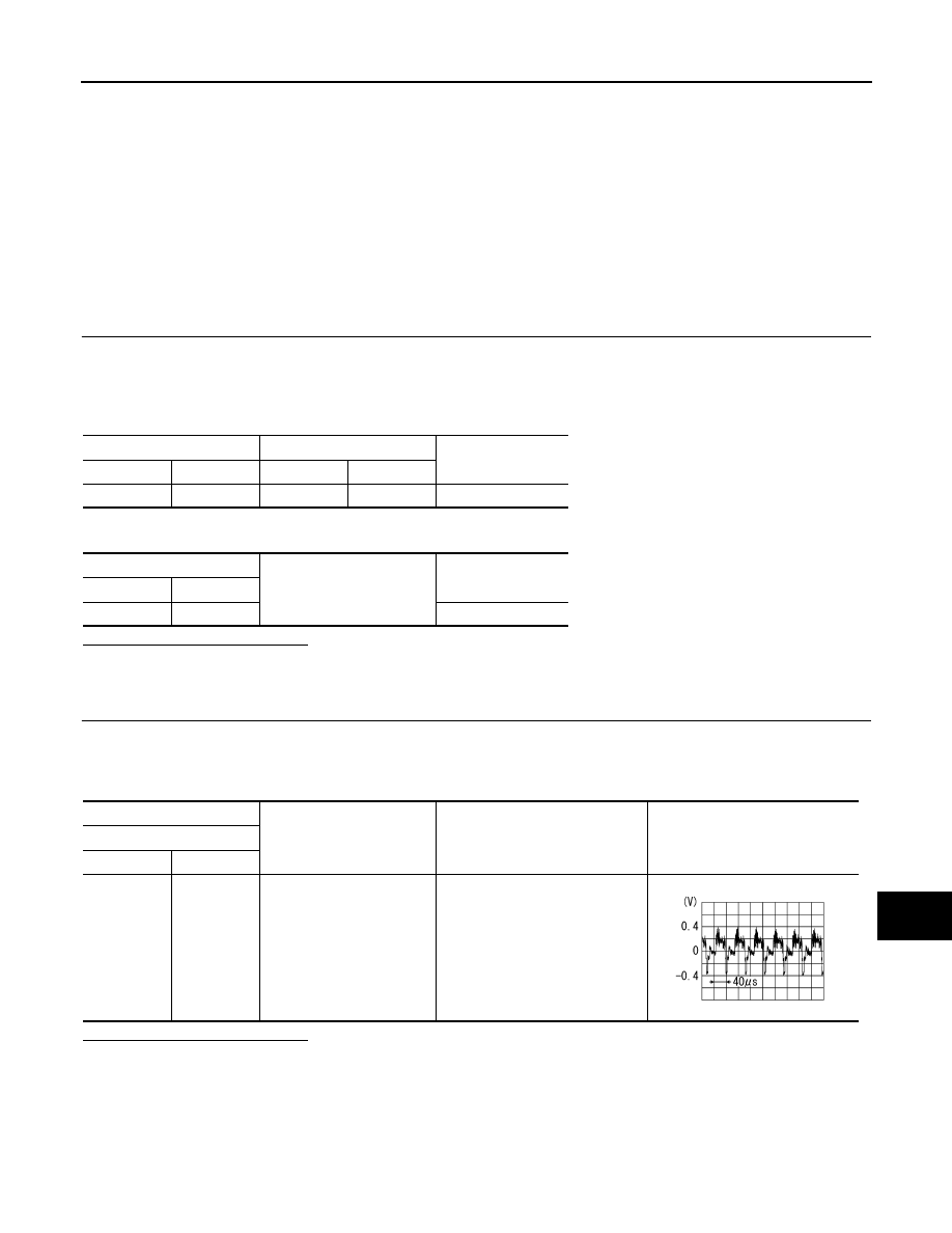
Check signal between camera control unit harness connector and ground using an oscilloscope.
Is the inspection result normal?
YES
>> Replace camera control unit.
NO
>> Replace rear view camera.
Camera control unit
Rear view camera
Continuity
Connector
Terminal
Connector
Terminal
B60
6
D192
3
Existed
Camera control unit
Ground
Continuity
Connector
Terminal
B60
6
Not existed
(+)
(
−
)
Condition
Signal
Camera control unit
Connector
Terminal
B60
6
Ground
Shift the selector lever to “R” posi-
tion.
SKIB2251J