содержание .. 1424 1425 1426 1427 ..
Nissan Murano Z51. Instruction - part 1426
P0720 OUTPUT SPEED SENSOR
TM-55
< DTC/CIRCUIT DIAGNOSIS >
[CVT: RE0F09B]
C
E
F
G
H
I
J
K
L
M
A
B
TM
N
O
P
P0720 OUTPUT SPEED SENSOR
Description
INFOID:0000000005513983
The secondary speed sensor detects the revolution of the CVT output shaft and emits a pulse signal. The
pulse signal is transmitted to the TCM, which converts it into vehicle speed.
DTC Logic
INFOID:0000000005513984
DTC DETECTION LOGIC
DTC CONFIRMATION PROCEDURE
CAUTION:
Always drive vehicle at a safe speed.
NOTE:
Immediately after performing any “DTC CONFIRMATION PROCEDURE”, always turn ignition switch OFF.
Then wait at least 10 seconds before performing the next test.
1.
CHECK DTC DETECTION
With CONSULT-III
1.
Turn ignition switch ON.
2.
Select “Data Monitor” in “TRANSMISSION”.
3.
Start engine and maintain the following conditions for at least 12 consecutive seconds.
With GST
Follow the procedure “With CONSULT-III”.
Is “P0720” detected?
YES
>> Go to
NO
>> Check intermittent incident. Refer to
GI-39, "Intermittent Incident"
.
Diagnosis Procedure
INFOID:0000000005513985
1.
CHECK SECONDARY SPEED SENSOR
With CONSULT-III
Check the pulse when vehicle drive.
Is the inspection result normal?
YES
>> GO TO 11.
NO
>> GO TO 2.
2.
CHECK POWER AND SENSOR GROUND
1.
Turn ignition switch OFF.
2.
Disconnect secondary speed sensor connector.
3.
Turn ignition switch ON.
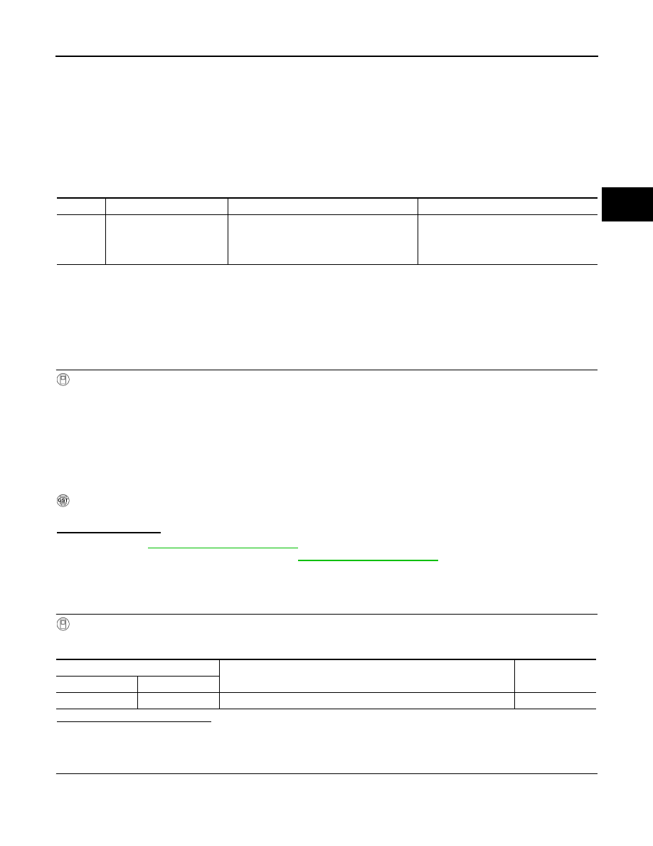
DTC
Trouble diagnosis name
DTC is detected if...
Possible cause
P0720
Output Speed Sensor Circuit
• Signal from secondary speed sensor is not
input due to open or short circuit.
• An unexpected signal is input during run-
ning.
• Harness or connectors
(Sensor circuit is open or shorted.)
• Secondary speed sensor
ACC PEDAL OPEN
: More than 1.0/8
RANGE
: “D” position
Driving location
: Driving the vehicle uphill (increased engine load) will help maintain the driving
conditions required for this test.
TCM connector
Condition
Data (Approx.)
Connector
Terminal
F23
34
When driving [“D” position, 20 km/h (12 MPH)]
350 Hz