содержание .. 784 785 786 787 ..
Nissan X-Trail 32. Instruction - part 786
P0300, P0301, P0302, P0303, P0304 MISFIRE
EC-273
< DTC/CIRCUIT DIAGNOSIS >
[MR20DD]
C
D
E
F
G
H
I
J
K
L
M
A
EC
N
P
O
2.
Disconnect corresponding A/F sensor 1 harness connector.
3.
Disconnect ECM harness connector.
4.
Check the continuity between A/F sensor 1 harness connector and ECM harness connector.
5.
Check the continuity between A/F sensor 1 harness connector and ground, or ECM harness connector
and ground.
6.
Also check harness for short to ground and short to power.
Is the inspection result normal?
YES
>> GO TO 14.
NO
>> Repair or replace malfunctioning part.
14.
CHECK A/F SENSOR 1 HEATER
EC-182, "Component Inspection"
Is the inspection result normal?
YES
>> GO TO 15.
NO
>> Replace malfunctioning A/F sensor 1. Refer to
.
15.
CHECK MASS AIR FLOW SENSOR OUTPUT VOLTAGE
WITH CONSULT
1.
Install all removed parts.
2.
Start engine and warm it up to normal operating temperature.
3.
Select “MAS A/F SE-B1” in “DATA MONITOR” mode with CONSULT and check the indication under the
following condition.
*: Check for linear voltage rise in response to increase of engine speed.
WITHOUT CONSULT
1.
Install all removed parts.
2.
Start engine and warm it up to normal operating temperature.
3.
Check the voltage between ECM harness connector terminals.
+
−
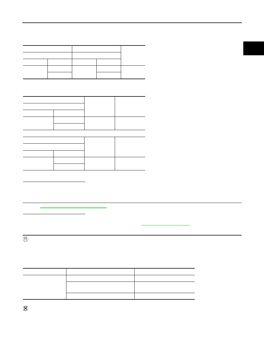
Continuity
A/F sensor 1
ECM
Connector
Terminal
Connector
Terminal
F27
1
F8
64
Existed
2
72
+
Ground
Continuity
A/F sensor 1
Connector
Terminal
F27
1
Ground
Not existed
2
+
Ground
Continuity
ECM
Connector
Terminal
F8
64
Ground
Not existed
72
Monitor item
Condition
Indication
MAS A/F SE-B1
Ignition switch ON (Engine stopped.)
Approx. 0.4 V
Idle (Engine is warmed-up to normal op-
erating temperature.)
0.7 - 1.2 V
Idle to about 4,000 rpm
0.7 - 1.2 V
→
2.4 V*