Nissan X-Trail 32. Instruction - part 1835


  Главная      Nissan     Nissan X-Trail 32 - Instruction


поиск по сайту           правообладателям


содержание   ..  1833  1834  1835  1836   ..


Nissan X-Trail 32. Instruction - part 1835


B121D STEERING LOCK POWER SUPPLY CIRCUIT

SEC-107

< DTC/CIRCUIT DIAGNOSIS >

[WITH INTELLIGENT KEY SYSTEM]

C

D

E

F

G

H

I

J

L

M

A

B

SEC

N

O

P

3.

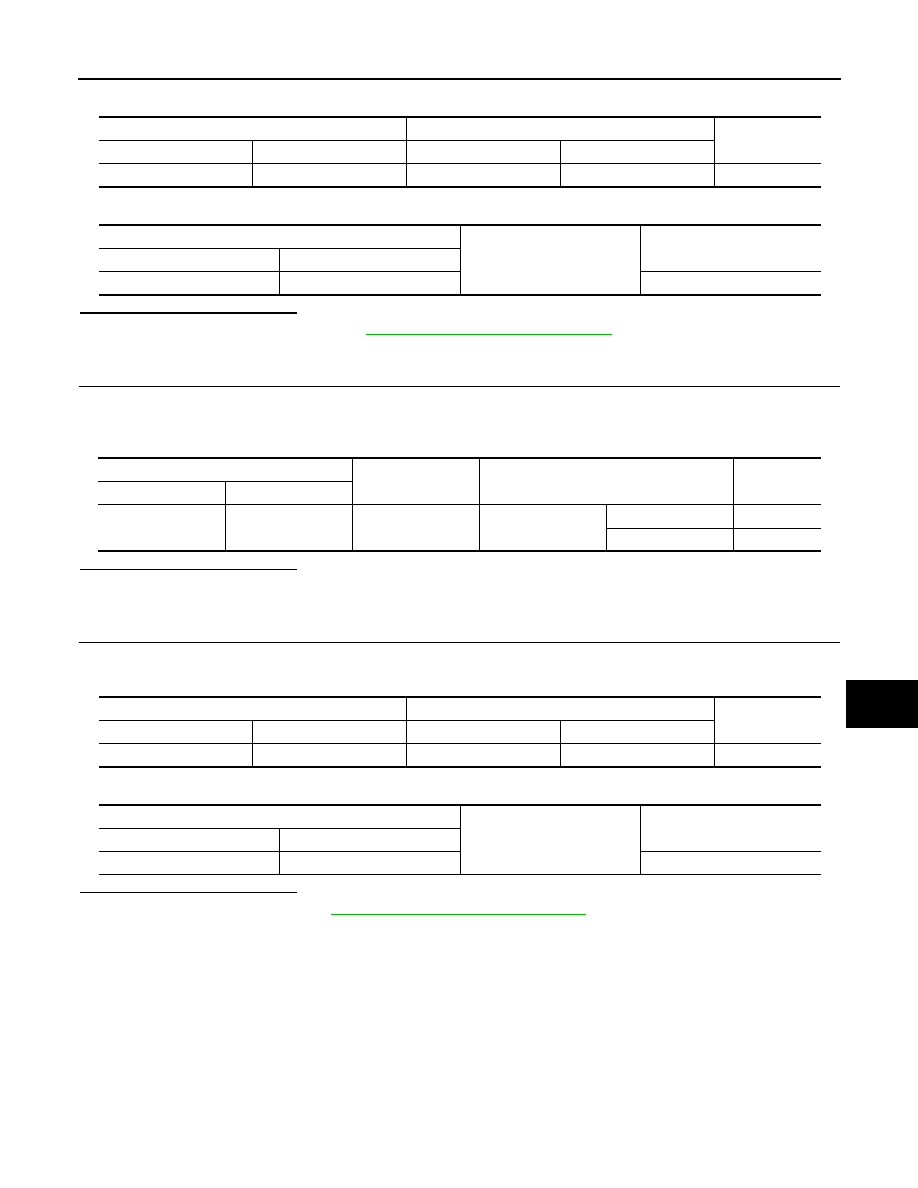
Check continuity between BCM harness connector and IPDM E/R harness connector.

4.

Check continuity between BCM harness connector and ground.

Is the inspection result normal?

YES

>> Replace IPDM E/R. Refer to 

PCS-60, "Removal and Installation"

.

NO

>> Repair or replace harness.

3.

CHECK STEERING LOCK UNIT INPUT SIGNAL

1.

Connect BCM connector.

2.

Disconnect steering lock unit connector.

3.

Check voltage between steering lock unit harness connector and ground.

Is the inspection result normal?

YES

>> Replace steering lock unit.

NO

>> GO TO 4.

4.

CHECK STEERING LOCK UNIT INPUT SIGNAL CIRCUIT

1.

Disconnect BCM connector.

2.

Check continuity between BCM harness connector and steering lock unit harness connector.

3.

Check continuity between BCM harness connector and ground.

Is the inspection result normal?

YES

>> Replace BCM. Refer to 

BCS-121, "Removal and Installation"

.

NO

>> Repair or replace harness.

IPDM E/R

BCM

Continuity

Connector

Terminal

Connector

Terminal

E10

3

E23

166

Existed

BCM

Ground

Continuity

Connector

Terminal

E23

166

Not existed

Steering lock unit

(-)

Condition

Voltage

Connector

Terminal

M57

2

Ground

Steering lock unit

Active

9 - 16 V

Not active

0 - 0.5 V

Steering lock unit

BCM

Continuity

Connector

Terminal

Connector

Terminal

M57

2

M87

41

Existed

BCM

Ground

Continuity

Connector

Terminal

M87

41

Not existed

SEC-108

< DTC/CIRCUIT DIAGNOSIS >

[WITH INTELLIGENT KEY SYSTEM]

B20DF STARTER RELAY OFF CIRCUIT

B20DF STARTER RELAY OFF CIRCUIT

DTC Description

INFOID:0000000010922231

DTC DETECTION LOGIC

POSSIBLE CAUSE

• Harness or connectors

(Starter relay circuit is open or shorted)

• IPDM E/R
• Starter motor

FAIL-SAFE

DTC CONFIRMATION PROCEDURE

1.

PERFORM DTC CONFIRMATION PROCEDURE

1.

Press push-button ignition switch under the following conditions, and wait 2 seconds or more.

-

Selector lever: In the P position

-

Brake pedal: Depressed

2.

Select “Self Diagnostic Result” mode of “IPDM E/R” using CONSULT.

Is DTC detected?

YES

>> Refer to 

SEC-108, "Diagnosis Procedure"

.

NO-1

>> To check malfunction symptom before repair: Refer to 

GI-44, "Intermittent Incident"

.

NO-2

>> Confirmation after repair: INSPECTION END

Diagnosis Procedure

INFOID:0000000010922232

1.

CHECK “S” TERMINAL CIRCUIT

1.

Turn ignition switch OFF.

2.

Disconnect starter motor connector.

3.

Shift selector lever to “P“or ”N” position.

4.

Check voltage between starter motor harness connector and ground.

MR20DD engine models

QR25DE engine models

DTC No.

CONSULT screen items

(Trouble diagnosis content)

DTC detecting condition

B20DF

STARTER RELAY 
OFF CIRC
(Starter relay off 
circuit)

[CIRC SHORT TO 
GROUND OR OPEN]

When IPDM E/R performs starter relay ON output but starter 
relay is OFF.

(+)

(-)

Condition

Voltage

Starter motor

Connector

Terminal

F47

2

Ground

When the ignition 

switch is in START po-

sition

12 V or more

(+)

(-)

Condition

Voltage

Starter motor

Connector

Terminal

F10

2

Ground

When the ignition 

switch is in START po-

sition

12 V or more

B20DF STARTER RELAY OFF CIRCUIT

SEC-109

< DTC/CIRCUIT DIAGNOSIS >

[WITH INTELLIGENT KEY SYSTEM]

C

D

E

F

G

H

I

J

L

M

A

B

SEC

N

O

P

R9M engine models

Is the inspection result normal?

YES

>> GO TO 2.

NO

>> GO TO 3.

2.

REPLACE STARTER MOTOR

Replace starter motor. Refer to the following procedure.
• MR20DD: 

STR-27, "MR20DD : Removal and Installation"

.

• QR25DE: 

STR-34, "QR25DE : Removal and Installation"

.

• R9M: 

STR-39, "R9M : Removal and Installation"

.

>> INSPECTION END

3.

CHECK STARTER MOTER INPUT SIGNAL CIRCUIT

1.

Turn ignition switch OFF.

2.

Disconnect IPDM E/R connector.

3.

Check continuity between starter motor harness connector and IPDM E/R harness connector.

MR20DD engine models

QR25DE engine models

R9M engine models

4.

Check continuity between IPDM E/R harness connector and ground.

Is the inspection result normal?

YES

>> GO TO 4.

NO

>> Repair or replace harness.

4.

REPLACE IPDM E/R

Replace IPDM E/R. Refer to 

PCS-60, "Removal and Installation"

.

>> INSPECTION END

(+)

(-)

Condition

Voltage

Starter motor

Connector

Terminal

F130

2

Ground

When the ignition 

switch is in START po-

sition

12 V or more

Starter motor

IPDM E/R

Continuity

Connector

Terminal

Connector

Terminal

F47

2

F73

81

Existed

Starter motor

IPDM E/R

Continuity

Connector

Terminal

Connector

Terminal

F10

2

F73

81

Existed

Starter motor

IPDM E/R

Continuity

Connector

Terminal

Connector

Terminal

F130

2

F73

81

Existed

IPDM E/R

Ground

Continuity

Connector

Terminal

F73

81

Not existed

SEC-110

< DTC/CIRCUIT DIAGNOSIS >

[WITH INTELLIGENT KEY SYSTEM]

B2190 CHAIN OF BCM - IMM ANT

B2190 CHAIN OF BCM - IMM ANT

DTC Description

INFOID:0000000010922143

DTC DETECTION LOGIC

POSSIBLE CAUSE

Harness or connectors
(NATS antenna amp. circuit is open or shorted.)
Intelligent Key
BCM

FAIL-SAFE

Inhibit engine cranking

DTC CONFIRMATION PROCEDURE

1.

PERFORM DTC CONFIRMATION PROCEDURE

1.

Make the conditions that BCM enters in the low power consumption mode (BCM sleep condition).
Refer to 

BCS-18, "POWER CONSUMPTION CONTROL SYSTEM : System Description"

.

2.

Turn ignition switch ON.

3.

Check to DTC in “Self Diagnostic Result” mode of “BCM” CONSULT.

Is DTC detected?

YES

>> Refer to 

SEC-110, "Diagnosis Procedure"

.

NO-1

>> To check malfunction symptom before repair: Refer to 

GI-44, "Intermittent Incident"

.

NO-2

>> Confirmation after repair: INSPECTION END

Diagnosis Procedure

INFOID:0000000010922144

1.

INTELLIGENT KEY REGISTRATION

Using CONSULT, register all Intelligent Keys again.

>> GO TO 2.

2.

CHECK SELF DIAGNOSTIC RESULT

1.

Select “Self Diagnostic Result” mode of “BCM” using CONSULT.

2.

Erase DTC.

3.

Perform DTC CONFIRMATION PROCEDURE for B2190-00. Refer to 

SEC-110, "DTC Description"

.

Is DTC detected?

YES

>> GO TO 3.

NO

>> INSPECTION END

3.

CHECK NATS ANTENNA COMMUNICATION SIGNAL

Check voltage signal between NATS antenna amp. harness connector and ground using an oscilloscope.

DTC No.

CONSULT screen items

(Trouble diagnosis content)

DTC detecting condition

B2190–00

CHAIN OF BCM-IMM ANT
(Chain of body control module - im-
mobilizer antenna)

When BCM cannot detect the Intelligent Key ID in 0.6 seconds.


содержание   ..  1833  1834  1835  1836   ..