содержание .. 157 158 159 160 ..
Nissan Primera P12. Instruction - part 159
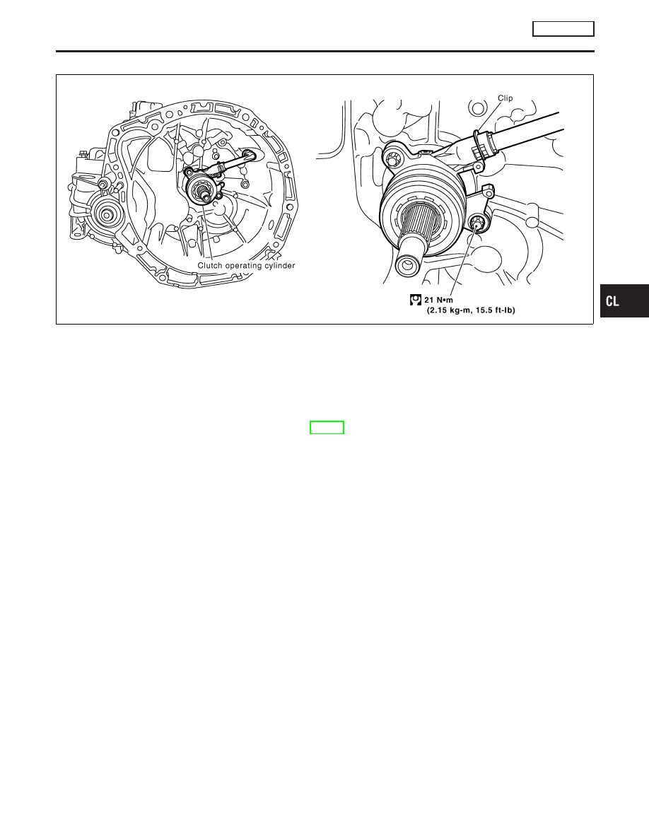
Components
NOCL0051
YCL077
Removal and Installation
NOCL0052
CAUTION:
Be careful not to splash brake fluid on painted areas; it may
cause paint damage. It brake fluid is splashed on painted
areas, wash it way with water immediately.
Refer to MT-10, “REMOVAL AND INSTALLATION”.
Inspection
NOCL0053
NOTE:
I
Cannot disassemble operating cylinder and release bearing
because they are integral parts. Replace them as an assem-
bly.
Inspect for the following, and replace parts if necessary
I
Operating cylinder: damage, foreign material, wear or pinholes
on the cylinder outer surface.
I
Release bearing: damage, incorrect rotation direction, or has
poor aligning function, and dust seal is deformed or cracked.
GI
MA
EM
LC
EC
FE
MT
AT
AX
SU
BR
ST
RS
BT
HA
SC
EL
IDX
CLUTCH RELEASE MECHANISM
RS6F93R
Components
CL-13