Nissan Qashqai J11. Instruction - part 945
SYSTEM
BRC-17
< SYSTEM DESCRIPTION >
[WITH ESP]
C
D
E
G
H
I
J
K
L
M
A
B
BRC
N
O
P
VALVE OPERATION (OTHER THAN ABS AND EBD)
Each valve is operated and fluid pressure of brake caliper is controlled.
NOTE:
There is no operation to hold and increase pressure for functions other than ABS and EBD.
When Pressure Increases
Component
FUNCTION
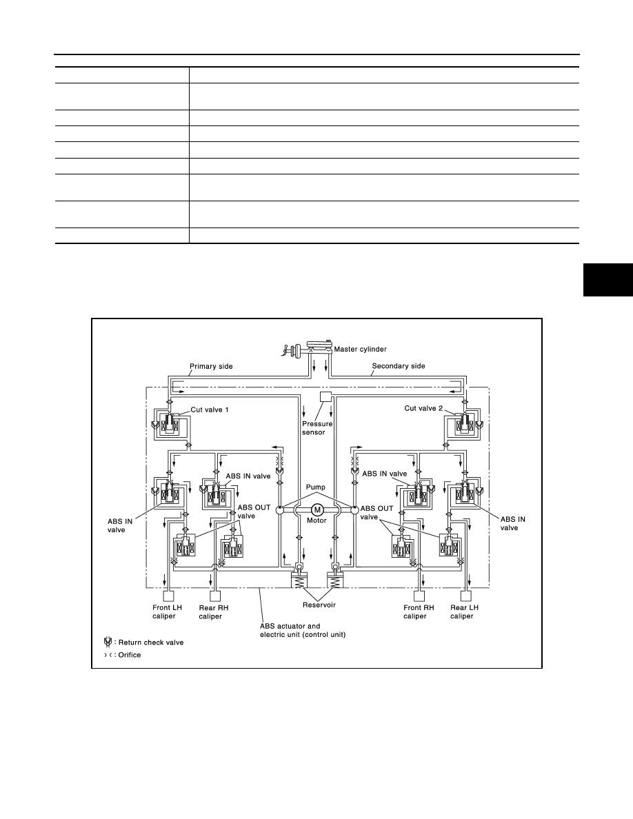
Reservoir
Temporarily reserves the brake fluid drained from brake caliper, so that pressure efficiently decreas-
es when decreasing pressure of brake caliper.
Pump
Returns the brake fluid reserved in reservoir to master cylinder by reducing pressure.
Motor
Drives the pump according to signals from control unit.
ABS IN valve
Switches the fluid pressure line to increase or hold according to signals from control unit.
ABS OUT valve
Switches the fluid pressure line to increase, hold or decrease according to signals from control unit.
Return check valve
Returns the brake fluid from brake caliper to master cylinder by bypassing orifice of each valve when
brake is released.
Cut valve 1
Cut valve 2
Performs the duty control of fluid pressure increased by pump according to signals from control unit.
Pressure Sensor
Detects the brake pedal operation amount.
JPFIC0162GB