Nissan Qashqai J11. Instruction - part 119
TIMING CHAIN
EM-415
< REMOVAL AND INSTALLATION >
[R9M]
C
D
E
F
G
H
I
J
K
L
M
A
EM
N
P
O
18. Remove the timing chain with the following procedure:
a.
the timing hydraulic tensioner,
b.
the timing chain tensioner guide,
c.
the exhaust camshaft timing sprocket bolts,
d.
the timing sprocket spacer,
e.
the crankshaft spacer,
f.
the "Exhaust camshaft timing sprocket (front) - timing chain - crankshaft sprocket" assembly,
g.
the timing chain guide,
h.
the tool [SST: — (Mot.1970)].
INSTALLATION
1.
Set the engine at TDC.
2.
Install the tool [SST: — (Mot.1970)].
3.
Install timing chain guide.
4.
Tighten timing chain guide bolts.
5.
Install the crankshaft sprocket onto the crankshaft.
6.
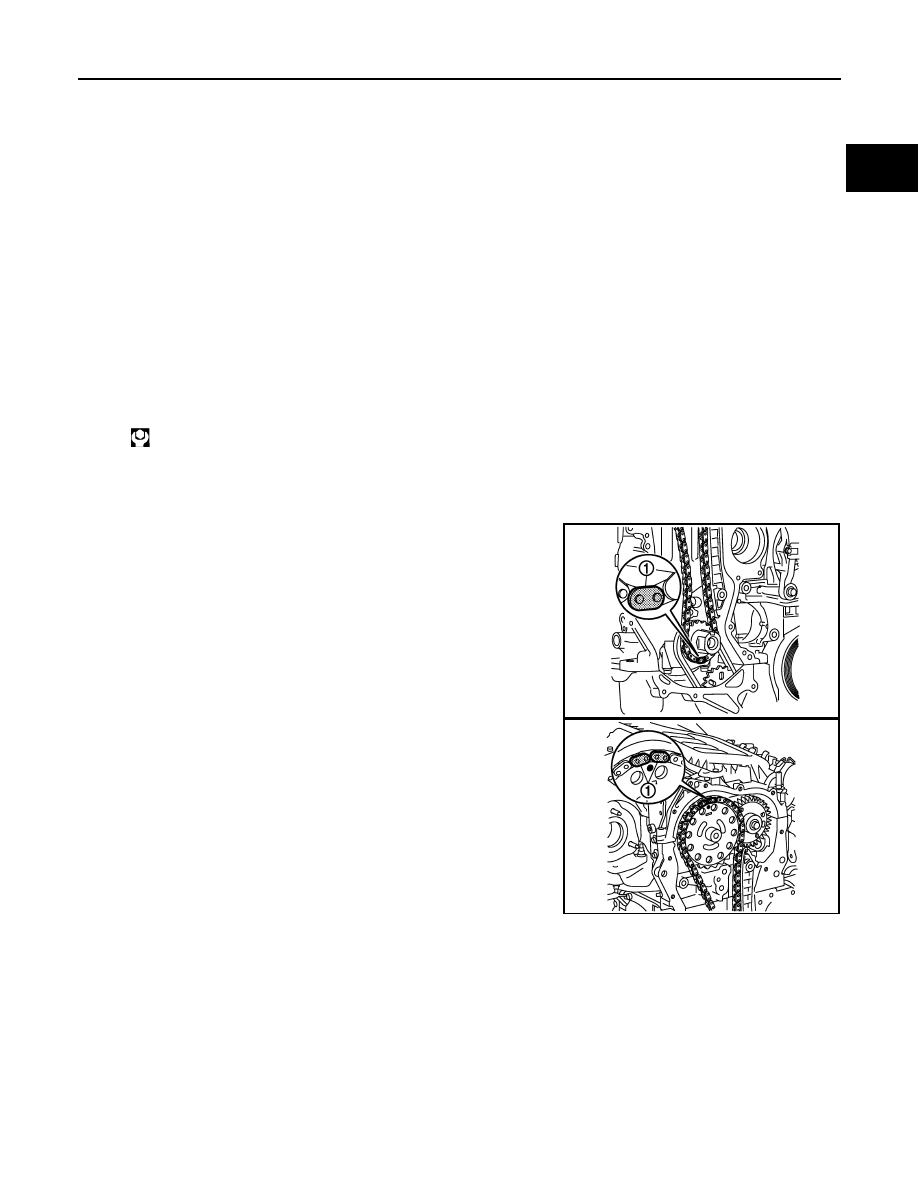
Position:
a.
the timing chain on the crankshaft sprocket (align the sprocket
mark with the cooper chain link (1)).
b.
the timing chain on the exhaust camshaft timing sprocket (front)
(align the sprocket mark with the cooper chain link (1)).
7.
Install the exhaust camshaft timing sprocket (front) onto the exhaust camshaft.
8.
Place the timing sprocket spacer on the exhaust camshaft timing sprocket (front).
9.
Finger tighten the exhaust camshaft timing sprocket bolts.
NOTE:
Allow the timing sprocket to rotate freely.
10. Install the crankshaft spacer.
11. Install the timing chain tensioner guide.
12. Tighten the bolt of the timing chain tensioner guide.
Timing chain guide bolts: 25 N·m (2.6 kg-m, 18
ft-lb)
E1BIA0593ZZ
E1BIA0592ZZ