Nissan Juke F15. Instruction - part 994


  Index      Nissan     Nissan Juke F15 (2015 year) - Service and Repair Instruction


Search            copyright infringement  


Content   ..  992  993  994  995   ..


Nissan Juke F15. Instruction - part 994


OUTSIDE MIRROR

MIR-19

< REMOVAL AND INSTALLATION >

C

D

E

F

G

H

I

J

K

M

A

B

MIR

N

O

P

CAUTION:

Perform side camera image calibration (with side camera). Refer to 

AV-116, "CALIBRATING CAMERA

IMAGE (AROUND VIEW MONITOR) : Description"

.

GLASS MIRROR
GLASS MIRROR : Removal and Installation

INFOID:0000000012201512

REMOVAL

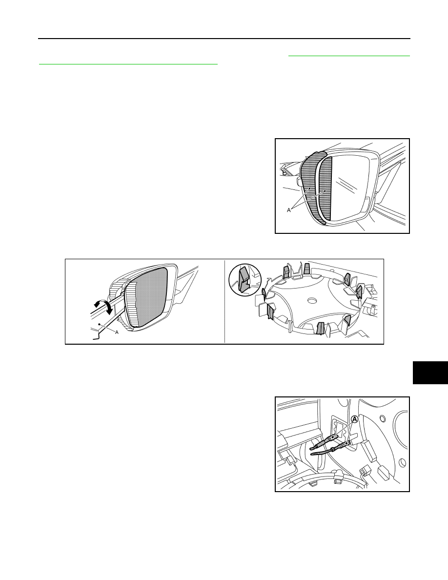
1. Place the glass mirror inward.
2. Apply protective tape (A) on door mirror housing and glass mir-

ror to protect it from damage.

3. Insert remover tool (A) into the recess at outside between glass mirror and door mirror actuator, and then

disengage the door mirror fixing pawls.

CAUTION:

Remove the pawls slowly so they are not damaged.

NOTE:

Insert remover tool into recesses,and push up while rotating (twisting) to make work easier.

4. Disconnect heater mirror terminals (A). (with heater mirror)

CAUTION:

Make a mark (short note, photo, etc.) of terminals layout,

before disassembly.

5. Remove glass mirror.

INSTALLATION

Note the following item, and then install in the reverse order of removal.

CAUTION:

After installation, visually check that pawls are securely engaged.

JMLIA5703ZZ

JMLIA5704ZZ

JMLIA4194ZZ

MIR-20

< REMOVAL AND INSTALLATION >

OUTSIDE MIRROR

DOOR MIRROR COVER
DOOR MIRROR COVER : Removal and Installation

INFOID:0000000012201513

REMOVAL

1. Remove the glass mirror. Refer to 

MIR-19, "GLASS MIRROR : Removal and Installation"

.

2. Remove door mirror finisher (without around view monitor sys-

tem) or side camera finisher (with around view monitor system)

fixing screws (A), disengage door mirror cover and door mirror

finisher (without around view monitor system) or side camera

finisher (with around view monitor system) fixing pawls pushed

in the direction of the arrows as shown in figure.

3. Disengage door mirror cover fixing pawls, and then remove door

mirror cover (1) and door mirror finisher (without around view

monitor system) or side camera finisher (with around view moni-

tor system) (2).

4. Disconnect side camera harness connector. (with around view monitor system)

5. Disengage door mirror cover fixing pawls, remove door mirror

cover (1) from door mirror finisher (without around view monitor

system) or side camera finisher (with around view monitor sys-

tem) (2) indicated by arrows as shown in the figure.

INSTALLATION

Note the following item and then install in the reverse order of removal.

CAUTION:

After installation, visually check that pawls are securely engaged.

JMLIA5686ZZ

: Pawl

JMLIA5687ZZ

JMLIA5688ZZ

DOOR MIRROR REMOTE CONTROL SWITCH

MIR-21

< REMOVAL AND INSTALLATION >

C

D

E

F

G

H

I

J

K

M

A

B

MIR

N

O

P

DOOR MIRROR REMOTE CONTROL SWITCH

Exploded View

INFOID:0000000012201514

Removal and Installation

INFOID:0000000012201515

REMOVAL

1. Remove the instrument lower panel. Refer to 

IP-13, "Removal and Installation"

.

2. Remove mounting screws and remove switch bracket from instrument lower panel.
3. Remove door mirror remote control switch (1) from switch

bracket (2) using remover tool (A).

INSTALLATION

Install in the reverse order of removal.

JMLIA1446ZZ

1.

Instrument lower panel 

2.

Switch bracket

3.

Door mirror remote control switch

: Pawl

JMLIA1447ZZ

MWI

MWI-1

DRIVER INFORMATION & MULTIMEDIA

C

D

E

F

G

H

I

J

K

L

M

B

SECTION 

MWI

A

O

P

CONTENTS

METER, WARNING LAMP & INDICATOR

PRECAUTION ...............................................

3

PRECAUTIONS ...................................................

3

Precaution for Supplemental Restraint System 
(SRS) "AIR BAG" and "SEAT BELT PRE-TEN-
SIONER" .................................................................
..

3

Precautions for Removing Battery Terminal  .............

3

PREPARATION ............................................

5

PREPARATION ...................................................

5

Commercial Service Tools  ........................................

5

SYSTEM DESCRIPTION  ..............................

6

COMPONENT PARTS  ........................................

6

METER SYSTEM .........................................................

6

METER SYSTEM : Component Parts Location  ........

6

METER SYSTEM : Component Description  .............

7

SYSTEM ..............................................................

8

METER SYSTEM .........................................................

8

METER SYSTEM : System Diagram ........................

8

METER SYSTEM : System Description ....................

8

METER SYSTEM : Fail-Safe ..................................

10

SPEEDOMETER ........................................................

11

SPEEDOMETER : System Diagram  .......................

11

SPEEDOMETER : System Description ...................

11

TACHOMETER ..........................................................

11

TACHOMETER : System Diagram .........................

12

TACHOMETER : System Description .....................

12

SHIFT POSITION INDICATOR ..................................

12

SHIFT POSITION INDICATOR : System Diagram ....

12

SHIFT POSITION INDICATOR : System Descrip-
tion ..........................................................................

13

OIL PRESSURE WARNING LAMP ...........................

13

OIL PRESSURE WARNING LAMP : System Dia-
gram ........................................................................

13

OIL PRESSURE WARNING LAMP : System De-
scription ...................................................................

13

METER ILLUMINATION CONTROL  .........................

13

METER ILLUMINATION CONTROL : System Di-
agram ......................................................................

14

METER ILLUMINATION CONTROL : System De-
scription ...................................................................

14

METER EFFECT FUNCTION  ....................................

14

METER EFFECT FUNCTION : System Diagram ....

15

METER EFFECT FUNCTION : System Descrip-
tion ...........................................................................

15

INFORMATION DISPLAY ..........................................

16

INFORMATION DISPLAY : System Diagram ..........

16

INFORMATION DISPLAY : System Description  .....

16

OPERATION .....................................................

20

Switch Name and Function ......................................

20

DIAGNOSIS SYSTEM (COMBINATION 
METER) .............................................................

21

On Board Diagnosis Function ..................................

21

CONSULT Function .................................................

22

ECU DIAGNOSIS INFORMATION ..............

26

COMBINATION METER  ...................................

26

Reference Value ......................................................

26

Fail-Safe ..................................................................

32

DTC Index  ...............................................................

33

IPDM E/R ...........................................................

35

List of ECU Reference .............................................

35

WIRING DIAGRAM ......................................

36

METER SYSTEM  ..............................................

36

Wiring Diagram ........................................................

36

BASIC INSPECTION  ...................................

46


Content   ..  992  993  994  995   ..