Nissan Juke F15. Instruction - part 422
P1807, P1808 BRAKE PEDAL POSITION SWITCH
EC-501
< DTC/CIRCUIT DIAGNOSIS >
[MR FOR NISMO RS MODELS]
C
D
E
F
G
H
I
J
K
L
M
A
EC
N
P
O
P1807, P1808 BRAKE PEDAL POSITION SWITCH
DTC Logic
INFOID:0000000013475492
DTC DETECTION LOGIC
DTC CONFIRMATION PROCEDURE
1.
PRECONDITIONING
If DTC Confirmation Procedure has been previously conducted, always perform the following procedure
before conducting the next test.
1. Turn ignition switch OFF and wait at least 10 seconds.
2. Turn ignition switch ON.
3. Turn ignition switch OFF and wait at least 10 seconds.
>> GO TO 2.
2.
PERFORM DTC CONFIRMATION PROCEDURE 1
With CONSULT
1. Turn ignition switch ON.
2. Select “BRAKE SW1” in “DATA MONITOR” mode of “ENGINE” using CONSULT.
3. Check “BRAKE SW1” indication as per the following conditions.
Without CONSULT
1. Turn ignition switch ON.
2. Check the voltage between ECM harness connector terminals as per the following.
Is the inspection result normal?
YES
>> GO TO 3.
NO
>> Proceed to
.
3.
PERFORM DTC CONFIRMATION PROCEDURE 2
1. Turn ignition switch ON.
2. Depress the brake pedal for at least 100 times.
3. Check DTC.
Is DTC detected?
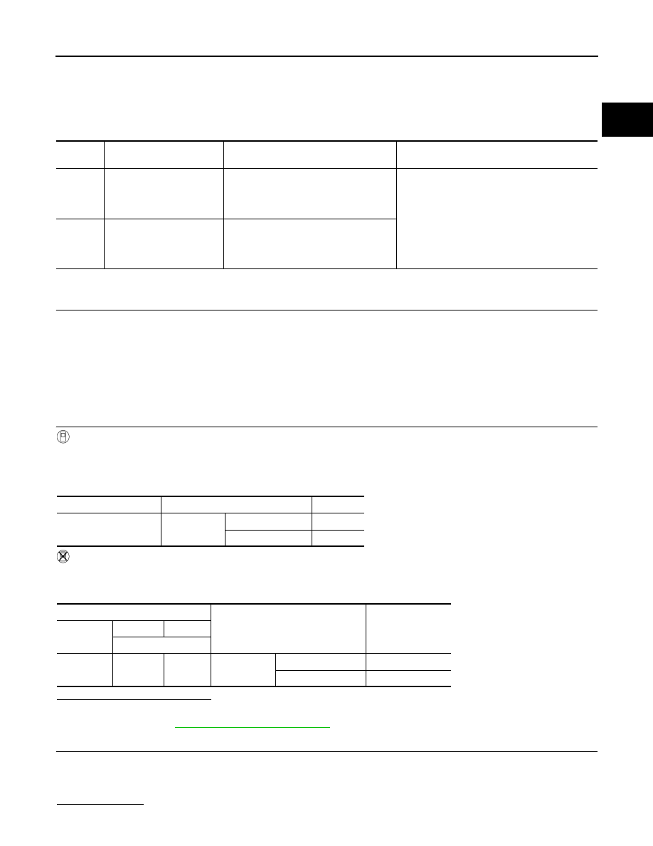
DTC No.
Trouble diagnosis name
(Trouble diagnosis content)
DTC detecting condition
Possible cause
P1807
Brake pedal position switch
(Brake pedal position
switch)
Regardless of ON/OFF of stop lamp
switch signal when brake pedal is de-
pressed 100 times, a brake pedal posi-
tion switch signal remains OFF.
• Harness or connectors
(Brake pedal position switch circuit is shorted.)
• Brake pedal position switch
• Incorrect brake pedal position switch installa-
tion
• ECM
P1808
Brake pedal position switch
(Brake pedal position
switch)
Regardless of ON/OFF of stop lamp
switch signal when brake pedal is de-
pressed 100 times, a brake pedal posi-
tion switch signal remains ON.
Monitor item
Condition
Indication
BRAKE SW1
Brake pedal
Slightly depressed
OFF
Fully released
ON
ECM
Condition
Voltage
(Approx.)
Connector
+
–
Terminal
E18
116
127
Brake pedal
Slightly depressed
0 V
Fully released
Battery voltage