Nissan Juke F15. Instruction - part 285
ELECTRIC CONTROLLED COUPLING
DLN-145
< REMOVAL AND INSTALLATION >
[REAR FINAL DRIVE: RTVS]
C
E
F
G
H
I
J
K
L
M
A
B
DLN
N
O
P
ELECTRIC CONTROLLED COUPLING
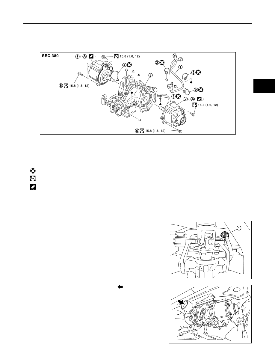
Exploded View
INFOID:0000000012199507
Removal and Installation
INFOID:0000000012199508
REMOVAL
1. Remove rear drive shaft. Refer to
RAX-19, "Removal and Installation"
2. Disconnect sub-harness connector (1).
3. Remove propeller shaft assembly. Refer to
4. Support rear final drive assembly with a suitable jack.
5. Remove rear final drive mounting bolt (
) at rear suspension
member.
1.
Sub-harness
2.
Band clip
3.
Rear final drive assembly
4.
Connector clip
5.
Electric controlled coupling (right)
6.
Reamer bolt
7.
Electric controlled coupling (left)
A.
Gear carrier mounting face
: Always replace after every disassembly.
: N·m (kg-m, ft-lb)
: Apply Genuine Liquid Gasket, Three Bond 1217 or equivalent.
JSDIA2237GB
JSDIA2135ZZ
JSDIA2136ZZ