Content .. 1027 1028 1029 1030 ..
Nissan Juke F15. Instruction - part 1029
PCS-60
< BASIC INSPECTION >
[POWER DISTRIBUTION SYSTEM]
DIAGNOSIS AND REPAIR WORK FLOW
BASIC INSPECTION
DIAGNOSIS AND REPAIR WORK FLOW
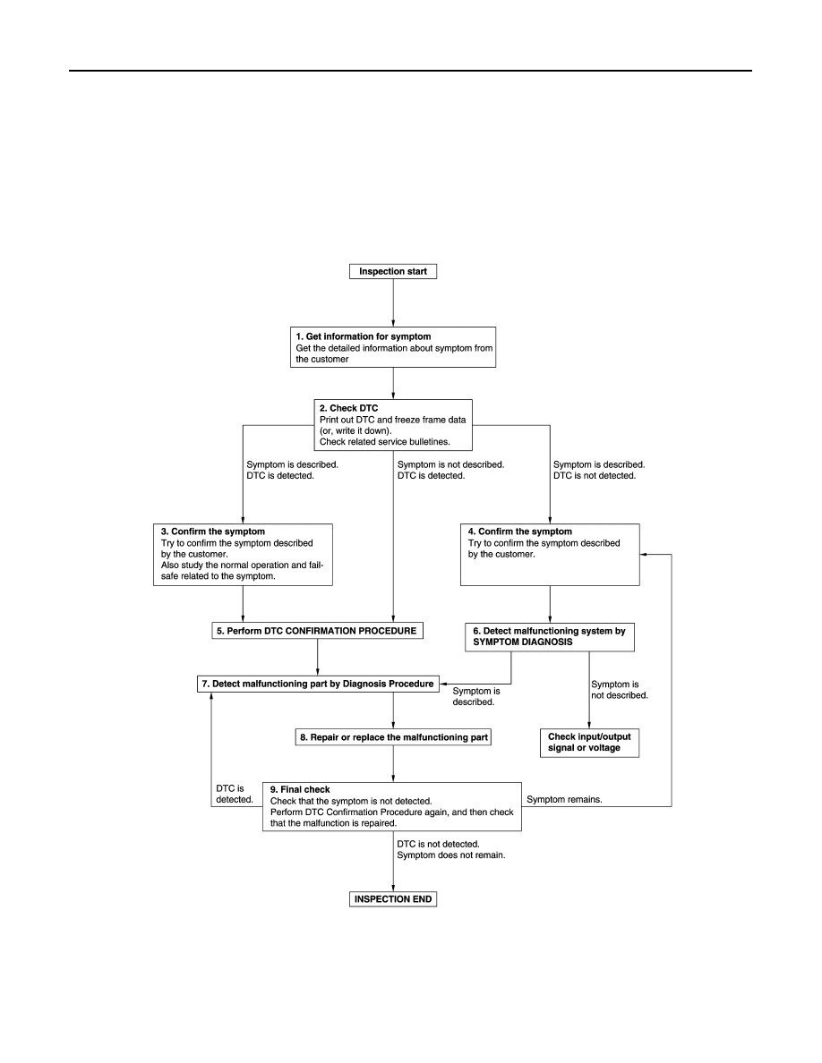
Work Flow
INFOID:0000000012197196
OVERALL SEQUENCE
DETAILED FLOW
JMKIA8652GB