Nissan Qashqai (2007-2010). Manual - part 1044


  Index      Nissan     Nissan Qashqai - service and repair manual 2007 - 2010 year


Search            copyright infringement  


Content   ..  1042  1043  1044  1045   ..


Nissan Qashqai (2007-2010). Manual - part 1044


FRONT DOOR LOCK

DLK-255

< ON-VEHICLE REPAIR >

[WITH I-KEY, WITHOUT SUPER LOCK]

C

D

E

F

G

H

I

J

L

M

A

B

DLK

N

O

P

FRONT DOOR LOCK

DOOR LOCK

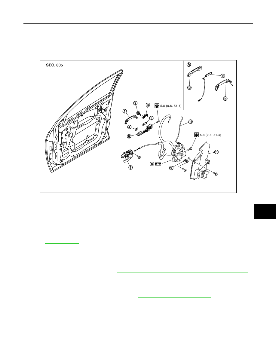
DOOR LOCK : Exploded View

INFOID:0000000000939224

DOOR LOCK : Removal and Installation

INFOID:0000000000939225

REMOVAL

1.

Remove the front door finisher. Refer to 

INT-10, "FRONT DOOR FINISHER : Removal and Installation"

.

2.

Remove the inside handle mounting bolt, and then disconnect the inside handle knob cable and the lock
knob cable.

3.

Remove the front door glass. Refer to 

GW-19, "Removal and Installation"

.

4.

Remove the front door module assembly. Refer to 

GW-22, "Removal and Installation"

.

5.

Disconnect the door antenna and the door request switch connector and remove the harness clamp
(models with Intelligent Key system).

1.

Outside handle assembly

2.

Door key cylinder

3.

 Key cylinder lever

4.

Front gasket

5.

Rear gasket 

6.

Outside handle bracket

7.

Inside handle

8.

Door lock assembly

9.

Key cylinder rod

10. Key rod protector

11.

Key rod protector assembly (RH 
handle only)

12. Outside handle cover

13. Antenna

14. Outside handle base

A:

Intelligent Key only

Refer to 

GI-4, "Components"

 for symbols in the figure.

JMKIA0188GB

DLK-256

< ON-VEHICLE REPAIR >

[WITH I-KEY, WITHOUT SUPER LOCK]

FRONT DOOR LOCK

6.

Remove the door side grommet, and remove the door key cylin-
der assembly (driver side) and outside handle escutcheon (pas-
senger side) mounting bolts from grommet hole.

CAUTION:

Do not forcibly remove the bolts (TORX: T10).

7.

Reach in to separate the key cylinder rod connection (on the handle). 

8.

Disconnect the door key cylinder switch harness connector. 

9.

Remove the key cylinder lever from the door key cylinder. 

10. While pulling the outside handle, remove door key cylinder

assembly.

11. Disconnect front door request switch harness connector (models with Intelligent Key system). 

12. While pulling outside handle, slide toward rear of vehicle to

remove outside handle.

13. Remove the front gasket and the rear gasket.

JMKIA0020ZZ

PIIB5809E

JMKIA0524ZZ

PIIB5811E

FRONT DOOR LOCK

DLK-257

< ON-VEHICLE REPAIR >

[WITH I-KEY, WITHOUT SUPER LOCK]

C

D

E

F

G

H

I

J

L

M

A

B

DLK

N

O

P

14. Remove the door lock assembly mounting bolts (TORX: T30).

15. Disconnect the door lock actuator connector, and then remove

the door lock assembly.

16. While pulling the outside handle bracket, slide toward rear of

vehicle to remove the outside handle bracket.

17. Reach in to separate the outside handle cable connection.

INSTALLATION

Install in the reverse order of removal.

CAUTION:

• To install each rod, rotate the rod holder until a click is felt.
• Check the door lock/unlock operation after installation. 
• Check the door open/close operation after installation. 

INSIDE HANDLE

INSIDE HANDLE : Exploded View

INFOID:0000000001091307

MIIB0633E

PIIB5814E

PIIB5815E

DLK-258

< ON-VEHICLE REPAIR >

[WITH I-KEY, WITHOUT SUPER LOCK]

FRONT DOOR LOCK

INSIDE HANDLE : Removal and Installation

INFOID:0000000001091308

REMOVAL

1.

Remove the front door finisher. Refer to 

INT-10, "FRONT DOOR FINISHER : Removal and Installation"

.

2.

Remove the inside handle mounting bolt.

3.

Disconnect the inside handle knob cable and the lock knob cable, and then remove the inside handle.

INSTALLATION

Install in the reverse order of removal.

CAUTION:

• Check the door lock/unlock operation after installation.
• Check the door open/close operation after installation.

OUTSIDE HANDLE

OUTSIDE HANDLE : Exploded View

INFOID:0000000001091309

1.

Outside handle assembly

2.

Door key cylinder

3.

 Key cylinder lever

4.

Front gasket

5.

Rear gasket 

6.

Outside handle bracket

7.

Inside handle

8.

Door lock assembly

9.

Key cylinder rod

10. Key rod protector

11.

Key rod protector assembly (RH 
handle only)

12. Outside handle cover

13. Antenna

14. Outside handle base

A:

Intelligent Key only

Refer to 

GI-4, "Components"

 for symbols in the figure.

JMKIA0188GB


Content   ..  1042  1043  1044  1045   ..