Nissan Tiida C11. Instruction - part 497


  Главная      Nissan     Nissan Tiida C11 - Instruction


поиск по сайту           правообладателям


содержание   ..  495  496  497  498   ..


Nissan Tiida C11. Instruction - part 497


EC-638

< ECU DIAGNOSIS >

[HR16DE (WITHOUT EURO-OBD)]

ECM

*: Accelerator pedal position sensor 2 signal and throttle position sensor 2 signal are converted by ECM internally. Thus, they differ from
ECM terminals voltage signal.
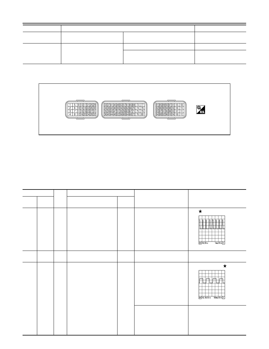
TERMINAL LAYOUT

PHYSICAL VALUES

NOTE:
• ECM is located in the engine room left side near battery. 
• Specification data are reference values and are measured between each terminal and ground.
• Pulse signal is measured by CONSULT-III.

CAUTION:

Do not use ECM ground terminals when measuring input/output voltage. Doing so may result in dam-
age to the ECMs transistor. Use a ground other than ECM terminals, such as the ground.

CRUISE LAMP

• Ignition switch: ON

MAIN switch: Pressed at the 1st time 


at the 2nd time

ON 

 OFF

SET LAMP

• MAIN switch: ON
• When vehicle speed: Between 40 

km/h (25 MPH) and 153 km/h (95 
MPH)

ASCD: Operating

ON

ASCD: Not operating

OFF

Monitor Item

Condition

Values/Status

PBIA9221J

Terminal No.

Wire 

color

Description

Condition

Value

(Approx.)

+

-–

Signal name

Input/

Output

1

Ground

L/W

Throttle control motor 
(Open)

Output

[Ignition switch: ON]
• Engine stopped
• Shift lever: D (A/T) or 1st (M/

T) 

• Accelerator pedal: Fully de-

pressed

3.2V

2

Ground

R/Y

Throttle control motor relay 
power supply

Input

[Ignition switch: ON]

BATTERY VOLTAGE
(11 - 14V)

3

Ground

LG/R

Heated oxygen sensor 1 
heater

Output

[Engine is running]
• Warm up condition
• Engine speed: Below 3,600 

rpm

Approximately 3.2V

[Engine is running]
• Warm-up condition
• Idle speed
[Engine is running]
• Engine speed: Above 3,600 

rpm

BATTERY VOLTAGE (11 - 14V)

PBIA8150J

PBIA8148J

ECM

EC-639

< ECU DIAGNOSIS >

[HR16DE (WITHOUT EURO-OBD)]

C

D

E

F

G

H

I

J

K

L

M

A

EC

N

P

O

4

Ground

P

Throttle control motor 
(Close)

Output

[Ignition switch: ON]
• Engine stopped
• Shift lever: D (A/T) or 1st (M/

T) 

• Accelerator pedal: Fully re-

leased

0 - 14V

5

Ground

R

Heated oxygen sensor 2 
heater

Output

[Engine is running]
• Engine speed: Below 3,900 

rpm after the following con-
ditions are met

- Engine: after warming up
- Keeping the engine speed 

between 3,500 and 4,000 
rpm for 1 minute and at idle 
for 1 minute under no load

10V

[Ignition switch: ON]
• Engine stopped
[Engine is running]
• Engine speed: Above 3,900 

rpm

BATTERY VOLTAGE
(11 - 14V)

9

Ground

W/B

EVAP canister purge volume 
control solenoid valve

Output

[Engine is running]
• Idle speed

BATTERY VOLTAGE

(11 - 14V)

[Engine is running]
• Engine speed: About 2,000 

rpm (More than 100 sec-
onds after starting engine.)

BATTERY VOLTAGE

(11 - 14V)

10

11

Ground

B

B/W

ECM ground

[Engine is running]
• Idle speed

Body ground

15

Ground

G/L

Throttle control motor relay

Output

[Ignition switch: OFF]

BATTERY VOLTAGE
(11 - 14V) 

[Ignition switch: ON]

0 - 1.0V

Terminal No.

Wire 

color

Description

Condition

Value

(Approx.)

+

-–

Signal name

Input/

Output

PBIA8149J

PBIA8148J

PBIB0050E

PBIB0520E

EC-640

< ECU DIAGNOSIS >

[HR16DE (WITHOUT EURO-OBD)]

ECM

17
18
21
22

Ground

L/Y

BR/Y

R/G

SB

Ignition signal No. 1
Ignition signal No. 2
Ignition signal No. 4
Ignition signal No. 3

Output

[Engine is running]
• Warm-up condition
• Idle speed

NOTE:
The pulse cycle changes de-
pending on rpm at idle

0 - 0.3V

[Engine is running]
• Warm-up condition
• Engine speed: 2,500 rpm

0.2 - 0.5V

23

Ground

B/O

Fuel pump relay

Output

[Ignition switch: ON]
• For 1 second after turning 

ignition switch ON

[Engine is running]

0 - 1.0V

[Ignition switch: ON]
• More than a few seconds af-

ter turning ignition switch 
ON

BATTERY VOLTAGE
(11 - 14V)

25
29
30
31

Ground

R/O

Y

O

L

Fuel injector No. 4
Fuel injector No. 3
Fuel injector No. 2
Fuel injector No. 1

Output

[Engine is running]
• Warm-up condition
• Idle speed

NOTE:
The pulse cycle changes de-
pending on rpm at idle

BATTERY VOLTAGE

(11 - 14V)

[Engine is running]
• Warm-up condition
• Engine speed: 2,000 rpm

BATTERY VOLTAGE

(11 - 14V)

32

Ground

Y/L

ECM relay
(Self shut-off)

Output

[Engine is running]
[Ignition switch: OFF]
• A few seconds after turning 

ignition switch OFF

0 - 1.0V

[Ignition switch: OFF]
• More than a few seconds af-

ter turning ignition switch 
OFF

BATTERY VOLTAGE
(11 - 14V)

Terminal No.

Wire 

color

Description

Condition

Value

(Approx.)

+

-–

Signal name

Input/

Output

PBIA9265J

PBIA9266J

PBIB0529E

PBIA4943J

ECM

EC-641

< ECU DIAGNOSIS >

[HR16DE (WITHOUT EURO-OBD)]

C

D

E

F

G

H

I

J

K

L

M

A

EC

N

P

O

33

Ground

L/R

Throttle position sensor 1

Input

[Ignition switch: ON]
• Engine stopped
• Shift lever: D (A/T) or 1st (M/

T)

• Accelerator pedal: Fully re-

leased

More than 0.36V

[Ignition switch: ON]
• Engine stopped
• Shift lever: D (A/T) or 1st (M/

T) 

• Accelerator pedal: Fully de-

pressed

Less than 4.75V

34

Ground

L/O

Throttle position sensor 2

Input

[Ignition switch: ON]
• Engine stopped
• Shift lever: D (A/T) or 1st (M/

T) 

• Accelerator pedal: Fully re-

leased

Less than 4.75V

[Ignition switch: ON]
• Engine stopped
• Shift lever: D (A/T) or 1st (M/

T)

• Accelerator pedal: Fully de-

pressed

More than 0.36V

36

Ground

V/W

Sensor ground
(Throttle position sensor)

[Engine is running]
• Warm-up condition
• Idle speed

0V

37

Ground

W

Knock sensor

Input

[Engine is running]
• Idle speed

2.5V

38

Ground

GR/B

Engine coolant temperature 
sensor

Input

[Engine is running]

0 - 4.8V
Output voltage varies with engine 
coolant temperature.

40

Ground

Sensor ground
(Knock sensor)

[Engine is running]
• Warm-up condition
• Idle speed

0V

41

Ground

G/P

Refrigerant pressure sensor

Input

[Engine is running]
• Warm-up condition
• Both A/C switch and blower 

fan motor switch: ON (Com-
pressor operates)

1.0 - 4.0V

44

Ground

B

Sensor ground
(Engine coolant temperature 
sensor)

[Engine is running]
• Warm-up condition
• Idle speed

0V

45

Ground

BR

Mass air flow sensor

Input

[Ignition switch ON]
• Engine stopped

0.4V

[Engine is running]
• Warm-up condition
• Idle speed

1.0 - 1.3V

[Engine is running]
• Warm-up condition
• Engine is revving from idle 

to about 4,000 rpm

1.0 - 1.3 to 2.4V (Check for linear 
voltage rise in response to en-
gine being increased to about 
4,000 rpm.)

46

Ground

V

Intake air temperature sen-
sor

Input

[Engine is running]

0 - 4.8V
Output voltage varies with intake 
air temperature.

Terminal No.

Wire 

color

Description

Condition

Value

(Approx.)

+

-–

Signal name

Input/

Output


содержание   ..  495  496  497  498   ..