Mazda B4000 4WD Truck (2004 year). Manual - part 3


  Index      Mazda     Mazda B4000 4WD Truck - service manual 2004 year in english


Search            


Content   ..  1  2  3  4   ..


Mazda B4000 4WD Truck (2004 year). Manual - part 3


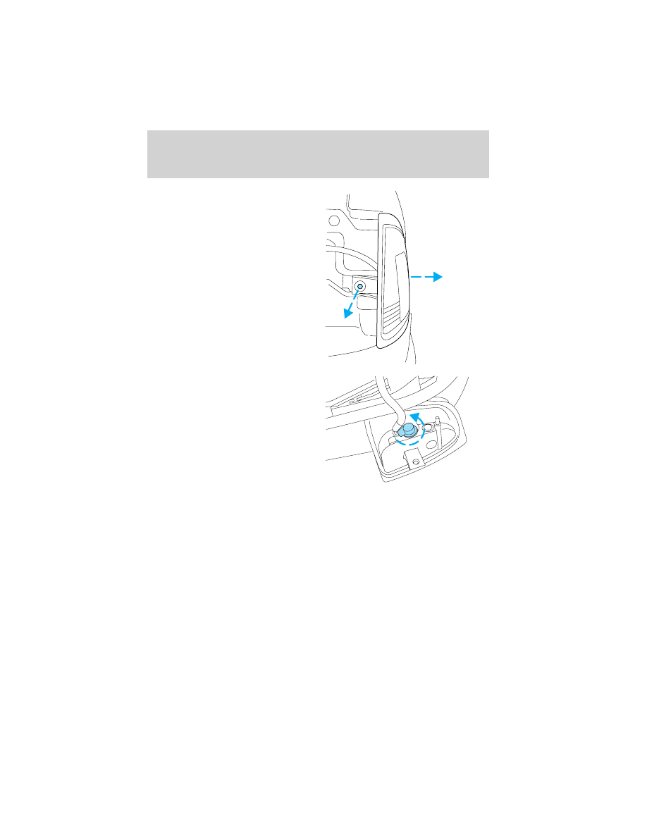
3. Remove screw(s) from lamp

assembly.

4. Disengage lamp assembly (it has

a snap fit).

5. Rotate bulb socket

counterclockwise and remove
from lamp assembly.

6. Carefully pull bulb straight out

of socket and push in the new
bulb.

7. Install the bulb socket in lamp

assembly by turning clockwise.

8. Align the lamp on the vehicle

and push to snap in place.

9. Install screw(s) on lamp assembly.

10. Install the headlamp on vehicle, push rearward and secure with two

retainer pins.

Lights

40

Replacing tail lamp/backup lamp bulbs

The tail lamp/backup lamp bulbs are
located in the same portion of the
tail lamp assembly, one just below
the other. Follow the same steps to
replace either bulb:

1. Open the tailgate to expose the

lamp assemblies.

2. Remove the four screws and the

lamp assembly from vehicle.

3. Rotate bulb socket

counterclockwise turn and
remove from lamp assembly.

4. Carefully pull the bulb straight

out of the socket and push in
the new bulb.

5. Install the bulb socket in lamp

assembly by turning clockwise.

6. Install the lamp assembly and

secure with four screws.

Replacing fog lamp bulbs

1. Remove the bulb socket from

the fog lamp by turning
counterclockwise.

2. Disconnect the electrical

connector from the fog lamp
bulb.

3. Connect the electrical connector to the new fog lamp bulb.

Lights

41

4. Install the bulb socket in the fog lamp turning clockwise.

Replacing high-mount brake lamp and cargo lamp bulbs

The replacement of the high-mount brake lamp bulb and cargo lamp bulb
is basically the same. This procedure covers the high-mount brake lamp
bulb.

To remove the brake lamp assembly:

1. Remove the two screws and

lamp assembly from vehicle.

2. Remove the bulb socket from

lamp assembly by rotating it counterclockwise.

3. Carefully pull bulb straight out of socket and push in the new bulb.

To install the brake lamp assembly:

1. Install the bulb socket into the lamp assembly by rotating clockwise.

2. Install the lamp assembly on the vehicle and secure with two screws.

Replacing license plate lamp bulbs

The license plate bulbs are located
behind the rear bumper. To change
the license plate lamp bulbs:

1. Reach behind the rear bumper

to locate the bulb socket.

2. Twist the socket

counterclockwise and remove.

3. Pull out the old bulb from

socket and push in the new
bulb.

4. Install the bulb socket in lamp assembly by turning it clockwise.

Lights

42

MULTI-FUNCTION LEVER

Windshield wiper: Rotate the end
of the control away from you to
increase the speed of the wipers
(from desired interval to low or high
speed position); rotate towards you
to decrease the speed of the wipers.

Windshield washer: Push the end
of the stalk:
• briefly: causes a single swipe of

the wipers without washer fluid.

• a quick push and hold: the wipers

will swipe three times with
washer fluid.

• a long push and hold: the wipers

and washer fluid will be activated
for up to ten seconds.

Windshield wiper blades

If the wiper blades do not wipe properly, clean both the windshield and
wiper blades using undiluted windshield wiper solution or a mild
detergent. Rinse thoroughly with clean water. To avoid damaging the
blades, do not use fuel, kerosene, paint thinner or other solvents.

Check the wiper blades for wear at least twice a year or when they seem
less effective. Substances such as tree sap and some hot wax treatments
used by commercial car washes reduce the effectiveness of wiper blades.

Driver Controls

Driver Controls

43

Changing the wiper blades

1. Pull the wiper arm away from

the vehicle. Turn the blade at an
angle from the wiper arm. Push
the lock pin manually to release
the blade and pull the wiper
blade down toward the
windshield to remove it from
the arm.

2. Attach the new wiper to the

wiper arm and press it into
place until a click is heard.

3. Replace wiper blades every 6 months for optimum performance.

TILT STEERING WHEEL (IF EQUIPPED)

To adjust the steering wheel:

1. Pull and hold the steering wheel

release control toward you.

2. Move the steering wheel up or

down until you find the desired
location.

3. Release the steering wheel

release control. This will lock
the steering wheel in position.

WARNING: Never adjust the steering wheel when the vehicle is
moving.

AUXILIARY POWER POINT

Power outlets are designed for
accessory plugs only. Do not
hang any type of accessory or
accessory bracket from the
plugs. Improper use of the
power outlets can cause damage
not covered by your warranty.

The auxiliary power points are
located on the instrument panel. Do
not plug optional electrical
accessories into the cigarette lighter.
Use the power points.

Do not use the power points for operating the cigarette lighter element.

The Maximum power each power point can supply depends on the fuse
rating. For example: a 20A fuse should supply a maximum of 240 Watts,
a 15A fuse should supply a maximum of 180 Watts and a 10A fuse should
supply a maximum of 120 Watts. Exceeding these limits will result in a
blown fuse. Refer to Passenger Compartment Fuse Panel in the
Roadside Emergencies chapter for fuse ratings in your vehicle.

Always keep the power point caps closed when not being used.

POWER WINDOWS (IF EQUIPPED)

WARNING: When closing the
power windows, you should
verify they are free of
obstructions and ensure that
children and/or pets are not in
the proximity of the window
openings.

Press and hold the bottom part of the rocker switch to open the window.
Press and hold the top part of the rocker switch to close the window.

Driver Controls

45

One touch down

Allows the driver’s window to open
fully without holding the control
down. Press completely down on
AUTO and release quickly. Press
again to stop.

AUTOMATIC DIMMING REAR VIEW MIRRORS (IF EQUIPPED)

When the inside rear view mirror detects bright light from behind the
vehicle, the inside rear view mirror will automatically darken to minimize
glare.

Do not block the sensor on the backside of the inside rear view mirror
since this may impair proper system performance.

Press the left button on the mirror
to turn the auto dimming ON or
OFF. The green indicator light left
of the display will illuminate when
this feature is ON.

COMPASS/TEMPERATURE EC MIRROR (IF EQUIPPED)

The compass reading may be affected when you drive near large
buildings, bridges, power lines and powerful broadcast antennas.
Magnetic or metallic objects placed in, on or near the vehicle may also
affect compass accuracy.

Usually, when something affects the compass readings, the compass will
correct itself after a few days of operating your vehicle in normal
conditions. If the compass still appears to be inaccurate, a manual
calibration may be necessary. Refer to Compass calibration
adjustment.

Most geographic areas (zones) have a magnetic north compass point that
varies slightly from the northerly direction on maps. This variation is four
degrees between adjacent zones and will become noticeable as the
vehicle crosses multiple zones. A correct zone setting will eliminate this
error. Refer to Compass zone adjustment.

Driver Controls

46

Outside air temperature

Display operation of the mirror with
the compass feature:
• Press the right button to toggle

the display between the compass
direction and no display.

Display operation of mirror with
temperature and compass feature:
• Press the right button once to

display temperature °F and
compass.

• Press the right button twice to display temperature °C and compass.
• Press the right button three times to turn the display OFF.

WARNING: The outside temperature indicator is not designed
to serve as an ICE warning device and is therefore unsuitable
for that purpose. Indicated temperatures just above the
freezing point does not guarantee that the road surface is free
of ice.

Compass zone adjustment

1. Determine which compass zone

you are in by referring to the
zone map.

2. Turn ignition to the ON

position.

1

2

3

4

5

6

7 8 9 1011

12

13

14

15

Driver Controls

47

3. To change the zone setting,

push and hold the right button
until ZONE appears in the
display.

4. Press the right button

repeatedly until desired
compass zone number is
displayed. The display will
change back to the compass
direction after 3 seconds when
the button is not activated.

Compass calibration adjustment

The compass calibrates itself under normal driving conditions. There is
not a need for manual compass calibration. If calibration is still desired,
follow these instructions:

1. Start the vehicle.

2. For optimum calibration, turn off all electrical accessories and make

sure that all vehicle doors are shut.

3. Perform this adjustment in an open area free from steel structures

and high voltage lines.

4. Press and hold the left button

for approximately 3 seconds
until CAL appears in the display.
Release the left button to enter
the calibration mode.

5. Drive the vehicle slowly (less

than 5 km/h [3 mph] in a circle
until CAL indicator disappears
in the display (about two or
three circles).

6. The compass is now calibrated.

Driver Controls

48

POWER MIRROR CONTROL (IF EQUIPPED)

To adjust your mirrors:

1. Select

to adjust the left

mirror or

to adjust the right

mirror.

2. Move the control in the

direction you wish to tilt the
mirror.

3. Return to the center position to

lock mirrors in place.

SPEED CONTROL (IF EQUIPPED)

With speed control set, you can maintain a speed of 48 km/h (30 mph)
or more without keeping your foot on the accelerator pedal. Speed
control does not work at speeds below 48 km/h (30 mph).

WARNING: Do not use the speed control in heavy traffic or on
roads that are winding, slippery, or unpaved. You may lose
control of the vehicle.

WARNING: Do not shift the gearshift lever into N (Neutral)
with the speed control on. You may lose control of the vehicle
or cause engine system damage.

Setting speed control

The controls for using your speed
control are located on the steering
wheel for your convenience.

1. Press the ON control and

release it.

2. Accelerate to the desired speed.

Driver Controls

49

3. Press the SET + control and

release it.

4. Take your foot off the

accelerator pedal.

5. The indicator light

on the

instrument cluster will turn on.

Note:
• Vehicle speed may vary momentarily when driving up and down a

steep hill.

• If the vehicle speed increases above the set speed on a downhill, you

may want to apply the brakes to reduce the speed.

• If the vehicle speed decreases more than 16 km/h (10 mph) below

your set speed on an uphill, your speed control will disengage.

• If the vehicle speed decreases to 40 km/h (25 mph) or less, your

speed control will disengage

Disengaging speed control

To disengage the speed control:
• Depress the brake pedal or
• Depress the clutch pedal (if equipped).
Disengaging the speed control will not erase previous set speed.

Note: When you use the clutch pedal to disengage the speed control,
the engine speed may briefly increase, this is normal.

Resuming a set speed

Press the RES (resume) control and
release it. This will automatically
return the vehicle to the previously
set speed. The RES control will not
work if the vehicle speed is not
faster than 48 km/h (30 mph).

Driver Controls

50

Increasing speed while using speed control

There are three ways to set a higher
speed:
• Press and hold the SET + control

until you get to the desired
speed, then release the control.

• Press and release the SET +

control to operate the Tap-Up function. Each tap will increase the set
speed by 1.6 km/h (1 mph).

• Use the accelerator pedal to get to the desired speed. When the

vehicle reaches that speed press and release the SET + control.

Reducing speed while using speed control

There are three ways to reduce a
set speed:
• Press and hold the CST - control

until you get to the desired
speed, then release the control.

• Press and release the CST -

control to operate the Tap-Down
function. Each tap will decrease the set speed by 1.6 km/h (1 mph).

• Depress the brake pedal or the

clutch pedal (if equipped) until
the desired vehicle speed is
reached, press the SET + control.

Turning off speed control

There are three ways to turn off the speed control:
• Depress the brake pedal or the clutch pedal (if equipped). This will

not erase your vehicle’s previously set speed.

Driver Controls

51

• Press the speed control OFF

control.

• Turn OFF the ignition.
Note: When you turn off the speed
control or the ignition, your speed
control set speed memory is erased.

Note: Fully depressing the clutch
pedal may cause a flare in engine RPM as the throttle is returned to idle.
This is normal.

OVERDRIVE CONTROL (IF EQUIPPED)

Activating overdrive

(Overdrive) is the normal drive position for the best fuel economy.

The overdrive function allows automatic upshifts and downshifts through
all available gears.

Deactivating overdrive

Press the Transmission Control
Switch (TCS) located on the end of
the gearshift lever. The O/D Off
indicator light will illuminate on the
instrument cluster. The transmission
will operate in all gears except overdrive.

To return to normal overdrive mode,
press the Transmission Control
Switch again. The O/D Off indicator
light will no longer be illuminated.

CENTER CONSOLE (IF EQUIPPED)

Your vehicle may be equipped with a
variety of console features. These
include:
• Utility compartment with

cassette/compact disc storage

• Cupholders
• Coin holder slots
• Flip up armrest

WARNING: Use only soft cups in the cupholder. Hard objects
can injure you in a collision.

BED EXTENDER (IF EQUIPPED)

Your vehicle may be equipped with a bed extender designed to extend
the pickup box for longer loads.

To extend the bed extender:

1. Lower tailgate.

2. Pull the round knobs on each

side of the extender to release
it from the pickup box.

3. Pivot extender on to the

tailgate.

4. Evenly push down on the

extender and push the round
knobs in on each side locking it
in place.

Green markings on the shaft
indicate the locked position. The
locking clip screws below the middle
bar can be tightened
counterclockwise for extra security.

Driver Controls

53

Note: If the red marking on the shaft is visible, the bed extender
is not locked or properly secured.

To stow the bed extender, follow steps one through four in reverse order.

The bed extender may be used to secure a load of up to 46 kg (100 lbs.)
on the tailgate.

The bed extender should always be kept in the stowed position
with the tailgate closed when not in use.

When driving the vehicle off road, the bed extender should be
removed and the tailgate closed.

To remove the bed extender:

1. Extend the bed extender.

2. Pull the round knobs on each

side of the extender to unlock
it.

Make sure the locking clip screws
are loose before removing the
extender.

3. Press the locking clips below

the middle bar on each side and
lift the extender out of the bed.

Note: Remove and store the bed extender when not in use.

To install the bed extender, follow the removal procedure in reverse
order.

Driver Controls

54

KEYS

The key operates all locks on your vehicle. In case of loss, replacement
keys are available from your dealer.

You should always carry a second key with you in a safe place in case
you require it in an emergency.

Refer to SecuriLock

Passive Anti-Theft System for more information.

POWER DOOR LOCKS (IF EQUIPPED)

Press the top of the control to
unlock all doors and the bottom to
lock all doors.

REMOTE ENTRY SYSTEM (IF EQUIPPED)

The remote entry system allows you to lock or unlock all vehicle doors
without a key.

The remote entry features only operate with the ignition in the LOCK
position.

If there is any potential remote keyless entry problem with your vehicle,
ensure ALL remote entry transmitters are brought to the dealership,
to aid in troubleshooting.

GENERAL INFORMATION: This device complies with part 15 of the FCC
rules and with RS-210 of Industry Canada. Operation is subject to the
following two conditions: (1) This device may not cause harmful
interference, and (2) This device must accept any interference received,
including interference that may cause undesired operation. Changes or
modifications not expressly approved by the party responsible for
compliance could void the user’s authority to operate the equipment.

This device complies with part 15 of the FCC rules and with RS-210 of
Industry Canada. Operation is subject to the following two conditions:
(1) This device may not cause harmful interference, and (2) This device
must accept any interference received, including interference that may
cause undesired operation.

UNLOCK

LOCK

Locks and Security

Locks and Security

55


Content   ..  1  2  3  4   ..