Lexus ES300 (2002 year). Service manual - part 425


  Index      Lexus     Lexus ES300 - service and repair manual 2002 year


Search            


Content   ..  423  424  425  426   ..


Lexus ES300 (2002 year). Service manual - part 425


C83129

C83128

C83127

C91929

C91928

-

AUTOMATIC TRANSMISSION / TRANS

AUTOMATIC TRANSAXLE ASSY (U150E)

40-63

85

U150E A/T REPAIR MANUAL   (RM913U)

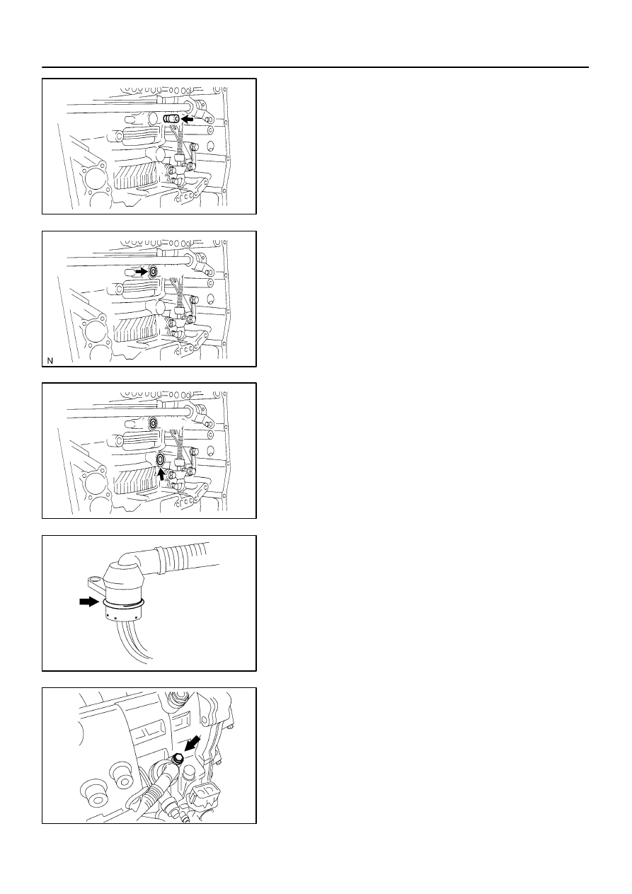
145. INSTALL BRAKE DRUM GASKET

(a)

Coat a new brake drum gasket with ATF, install it to the
transaxle case.

146. INSTALL TRANSAXLE CASE 2ND BRAKE GASKET

(a)

Coat a new transaxle case 2nd brake gasket with ATF,
install it to the transaxle case.

147. INSTALL GOVERNOR APPLY GASKET NO.1

(a)

Coat a new governor apply gasket No. 1 with ATF, install
it to the transaxle case.

148. INSTALL TRANSMISSION WIRE

(a)

Coat a new O-ring with ATF, install it to the transmission
wire.

(b)

Install the transmission wire retaining bolt.
Torque: 5.4 N

m (55 kgf

cm, 48 in.

lbf)

C91927

C91933

A

C

B

B

A

C


C91932

C91931

40-64

-

AUTOMATIC TRANSMISSION / TRANS

AUTOMATIC TRANSAXLE ASSY (U150E)

86

U150E A/T REPAIR MANUAL   (RM913U)

149. CONNECT TRANSMISSION WIRE

(a)

Coat a O-ring of the ATF temperature sensor with ATF.

(b)

Install the ATF temperature sensor, with the lock plate and
bolt.
Torque: 6.6 N

m (67 kgf

cm, 58 in.

lbf)

(c)

Connect the 7 solenoid connectors.

150. INSTALL TRANSMISSION VALVE BODY ASSY

(a)

Make sure that the manual valve lever position, install the
valve body with 17 bolts to the transaxle case.
Torque: 10.8 N

m (110 kgf

cm, 8 ft

lbf)

Bolt length:
Bolt A: 25 mm (0.984 in.)
Bolt B: 57 mm (2.244 in.)
Bolt C: 41 mm (1.614 in.)

NOTICE:


Push the valve body against the accumulator piston
spring and the check ball body to install it.


When installing the valve body to the transaxle case,
do not hold the solenoids.


Tighten temporarily those bolts marked by 


 in the il-

lustration first because they are positioning bolts.

151. INSTALL VALVE BODY OIL STRAINER ASSY

(a)

Coat a new O-ring with ATF, install it to the oil strainer.

(b)

Install the oil strainer and 3 bolts to the valve body.
Torque: 10.8 N

m (110 kgf

cm, 8 ft

lbf)

C91926

Magnet

C91925

D26716

D03900

D03900

-

AUTOMATIC TRANSMISSION / TRANS

AUTOMATIC TRANSAXLE ASSY (U150E)

40-65

87

U150E A/T REPAIR MANUAL   (RM913U)

152. INSTALL AUTOMATIC TRANSAXLE OIL PAN

SUB-ASSY

(a)

Install the 3 magnets in the oil pan.

(b)

Apply seal packing or equivalent to new 18 bolts.
Seal packing:
THREE BOND 2430 or equivalent

(c)

Install the oil with the 18 bolts to the transaxle case.
Torque: 7.8 N

m (80 kgf

cm, 69 in.

lbf)

NOTICE:
Because the bolts should be seal bolts, apply seal packing
to new bolts and tighten them within 10 minutes after ap-
plication.

153. INSTALL TRANSAXLE CASE NO.1 PLUG

(a)

Coat the 4 new O-rings with ATF, install them to the 4
transaxle case No. 1 plugs.

(b)

Install the 4 transaxle case No. 1 plugs to the transaxle
case.
Torque: 7.4 N

m (75 kgf

cm, 65 in.

lbf)

154. INSTALL SPEED SENSOR(AISIN -MADE)

(a)

Coat the 2 new O-rings with ATF, install them to the 2 sen-
sors.

(b)

Install the 2 sensors to the transaxle case with the 2 bolts.
Torque: 11.3 N

m (115 kgf

cm, 8 ft

lbf)

155. INSTALL SPEED SENSOR(TMC -MADE)

(a)

Coat the 2 new O-rings with ATF, install them to the 2 sen-
sors.

(b)

Install the 2 sensors to the transaxle case with the 2 bolts.
Torque: 11.3 N

m (115 kgf

cm, 8 ft

lbf)

C83144

C83143

D09639

D09640

40-66

-

AUTOMATIC TRANSMISSION / TRANS

AUTOMATIC TRANSAXLE ASSY (U150E)

88

U150E A/T REPAIR MANUAL   (RM913U)

156. INSTALL OIL COOLER TUBE UNION(OUTLET OIL

COOLER UNION)

(a)

Coat a new O-ring with ATF, install it to the elbow.

(b)

Install the elbow to the transaxle case.
Torque: 27 N

m (276 kgf

cm, 20 ft

lbf)

157. INSTALL OIL COOLER TUBE UNION(INLET OIL

COOLER UNION)

(a)

Coat a new O-ring with ATF, install it to the union.

(b)

Install the union to the transaxle case.
Torque: 27 N

m (276 kgf

cm, 20 ft

lbf)

158. INSTALL BREATHER PLUG HOSE

159. INSTALL PARK/NEUTRAL POSITION SWITCH ASSY

(a)

Install the park/neutral position switch onto the manual
valve lever shaft and temporarily install the 2 adjusting
bolts.

(b)

Install a new nut stopper and nut.
Torque: 6.9 N

m (70 kgf

cm, 61 in.

lbf)

(c)

Temporarily install control shaft lever.


Content   ..  423  424  425  426   ..