Lexus ES300 (2002 year). Service manual - part 375


  Index      Lexus     Lexus ES300 - service and repair manual 2002 year


Search            


Content   ..  373  374  375  376   ..


Lexus ES300 (2002 year). Service manual - part 375


-

DIAGNOSTICS

SFI SYSTEM (1MZ-FE)

05-1 19

272

2002 LEXUS ES300 REPAIR MANUAL   (RM911U)

5

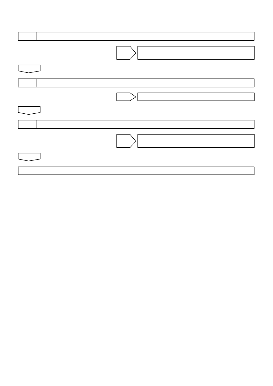
CHECK HARNESS AND CONNECTOR(ECM - THROTTLE BODY ASSY)

NG

REPAIR OR REPLACE HARNESS AND
CONNECTOR

OK

6

INSPECT E.F.I. THROTTLE POSITION SENSOR (See Page 

10-2

)

NG

REPLACE E.F.I. THROTTLE POSITION SENSOR

OK

7

CHECK HARNESS AND CONNECTOR(ECM - THROTTLE POSITION SESOR)

NG

REPAIR OR REPLACE HARNESS AND
CONNECTOR

OK

CHECK AND REPLACE ECM

051ZE-12

-

DIAGNOSTICS

SFI SYSTEM (1MZ-FE)

05-5

158

2002 LEXUS ES300 REPAIR MANUAL   (RM911U)

PRE-CHECK

1.

DIAGNOSIS SYSTEM

(a)

Description


When troubleshooting OBD II vehicles, the only dif-
ference from the usual troubleshooting procedure
is that you connect the vehicle to the OBD II scan
tool complying with SAE J1978 or hand-held tester,
and read off various data output from the vehicle’s
ECM.


OBD II regulations require that the vehicle’s  on-
board computer lights up the Malfunction Indicator
Lamp (MIL) on the instrument panel when the com-
puter detects a malfunction in the emission control
system/components  or in the powertrain control
components which affect vehicle emissions, or a
malfunction in the computer. In addition to the MIL
lighting up when a malfunction is detected, the ap-
plicable Diagnostic Trouble Codes (DTCs) pre-
scribed by SAE J2012 are recorded in the ECM
memory (See page 

05-18

).

If the malfunction does not reoccur in 3 consecutive trips, the
MIL goes off automatize but the DTC remain recorded in the
ECM memory.


To check the DTC, connect the OBD II scan tool or
hand-held  tester to the Data Link Connector 3
(DLC3) on the vehicle. The OBD II scan tool or
hand-held  tester also enables you to erase the
DTC and check freezed frame data and various
forms of engine data (For operating instructions,
see the OBD II scan tool’s instruction book.). DTC
include SAE controlled codes and manufacturer
controlled codes. SAE controlled codes must be set
as prescribed by the SAE, while manufacturer con-
trolled codes can be set freely by the manufacturer
within the prescribed limits (See DTC chart on page

05-18

).


The diagnosis system operates in normal mode
during normal vehicle use. It also has a check mode
for technicians to simulate malfunction symptoms
and troubleshoot. Most DTC use 2 trip detection
logic* to prevent erroneous detection, and ensure
thorough malfunction detection. By switching the
ECM to check mode when troubleshooting, the
technician can cause the MIL to light up for a mal-
function that is only detected once or momentarily
(hand-held tester only). (See step 2)

3

2

1

4 5 6 7 8

9 10111213141516

DLC3

A04550

05-6

-

DIAGNOSTICS

SFI SYSTEM (1MZ-FE)

159

2002 LEXUS ES300 REPAIR MANUAL   (RM911U)


*2 trip detection logic:
When a malfunction is first detected, the malfunc-
tion is temporarily stored in the ECM memory. (1st
trip)

If the same malfunction is detected again during the second
drive test, this second detection causes the MIL to light up. (2nd
trip) the 2 trip repeats the same mode a 2nd time (However, the
ignition switch must be turned OFF between the 1st trip and 2nd
trip.).


Freeze frame data:
Freeze frame data records the engine condition
when a misfire (DTCs P0300 - P0306) or fuel trim
malfunction (DTCs P0171 and P0172) or other mal-
function (first malfunction only), is detected. Be-
cause freeze frame data records the engine condi-
tions (fuel system, calculated load, engine coolant
temperature, fuel trim, engine speed, vehicle
speed, etc.) when the malfunction is detected.
When  troubleshooting, it is useful for determining
whether the vehicle was running or stopped, the en-
gine was warmed up or not, the air-fuel ratio was
lean or rich, etc. at the time of the malfunction.

Priorities for troubleshooting:
If troubleshooting priorities for multiple DTCs are given in the
applicable DTC chart, these should be followed.
If no instructions are given, troubleshoot DTCs according to the
following priorities.

(1)

DTC other than fuel trim malfunction (DTCs P0171
and P0172), and misfire (DTCs P0300 - P0306).

(2)

Fuel trim malfunction (DTCs P0171 and P0172).

(3)

Misfire (DTCs P0300 - P0306).

(b)

Check the DLC3.
The vehicle’s ECM uses ISO 9141-2 for communication.
The terminal arrangement of DLC3 complies with SAE
J1962 and matches the ISO 9141-2  format.

Terminal No.

Connection/Voltage or Resistance

Condition

7

Bus + Line/Pulse generation

During transmission

4

Chassis Ground 

 Body Ground/1 

 or less

Always

16

Battery Positive 

 Body Ground/9 - 14 V

Always

FI0534

-

DIAGNOSTICS

SFI SYSTEM (1MZ-FE)

05-7

160

2002 LEXUS ES300 REPAIR MANUAL   (RM911U)

HINT:
If your display shows UNABLE TO CONNECT TO VEHICLE
when you have connected the cable of the OBD II scan tool or
TOYOTA hand-held tester to the DLC3, turned the ignition
switch ON and operated the scan tool, there is a problem on the
vehicle side or tool side.


If communication is normal when the tool is connected to
another vehicle, inspect the DLC3 on the original vehicle.


If communication is still not possible when the tool is con-
nected to another vehicle, the problem is probably in the
tool itself, so consult the Service  Department listed in the
tool’s instruction manual.

2.

INSPECT DIAGNOSIS (Normal Mode)

(a)

Check the MIL.
(1)

The MIL comes on when the ignition switch is turned
ON and the engine is not running.

HINT:
If the MIL does not light up, troubleshoot the combination meter
(See page 

05-1040

).

(2)

When the engine started, the MIL should go off. If
the lamp remains on, the diagnosis system has de-
tected a malfunction or abnormality in the system.

(b)

Check the DTC.

NOTICE:


If there is no DTC in the normal mode, check the 1st
trip DTC using Continuous Test Results function
(Mode 7 for SAE J1979) or the OBD II scan tool or
hand-held  tester.


Hand-held tester only:
When the diagnosis system is switched from the nor-
mal mode to the check mode, it erases all DTC and
freezed frame data recorded in the normal mode. So
before switching modes, always check the DTC and
freezed frame data, and note them down.
(1)

Prepare the OBD II scan tool (complying with SAE
J 1978) or hand-held tester.

(2)

Connect the OBD II scan tool or hand-held tester
to the DLC3 at the lower center of the instrument
panel.

(3)

Turn the ignition switch ON and push the OBD II
scan tool or hand-held tester switch ON.

(4)

Use the OBD II scan tool or hand-held tester to
check the DTC and freezed frame data and note
them down (For operating instructions, see the
OBD II scan tool’s instruction book.).
If there is no DTC in the normal mode, check the 1st
trip DTC using Continuous Test Results function
(Mode 7 for SAE J1979) on the OBD II scan tool or
hand-held  tester.


Content   ..  373  374  375  376   ..