Lexus ES300 (2002 year). Service manual - part 360
A61585
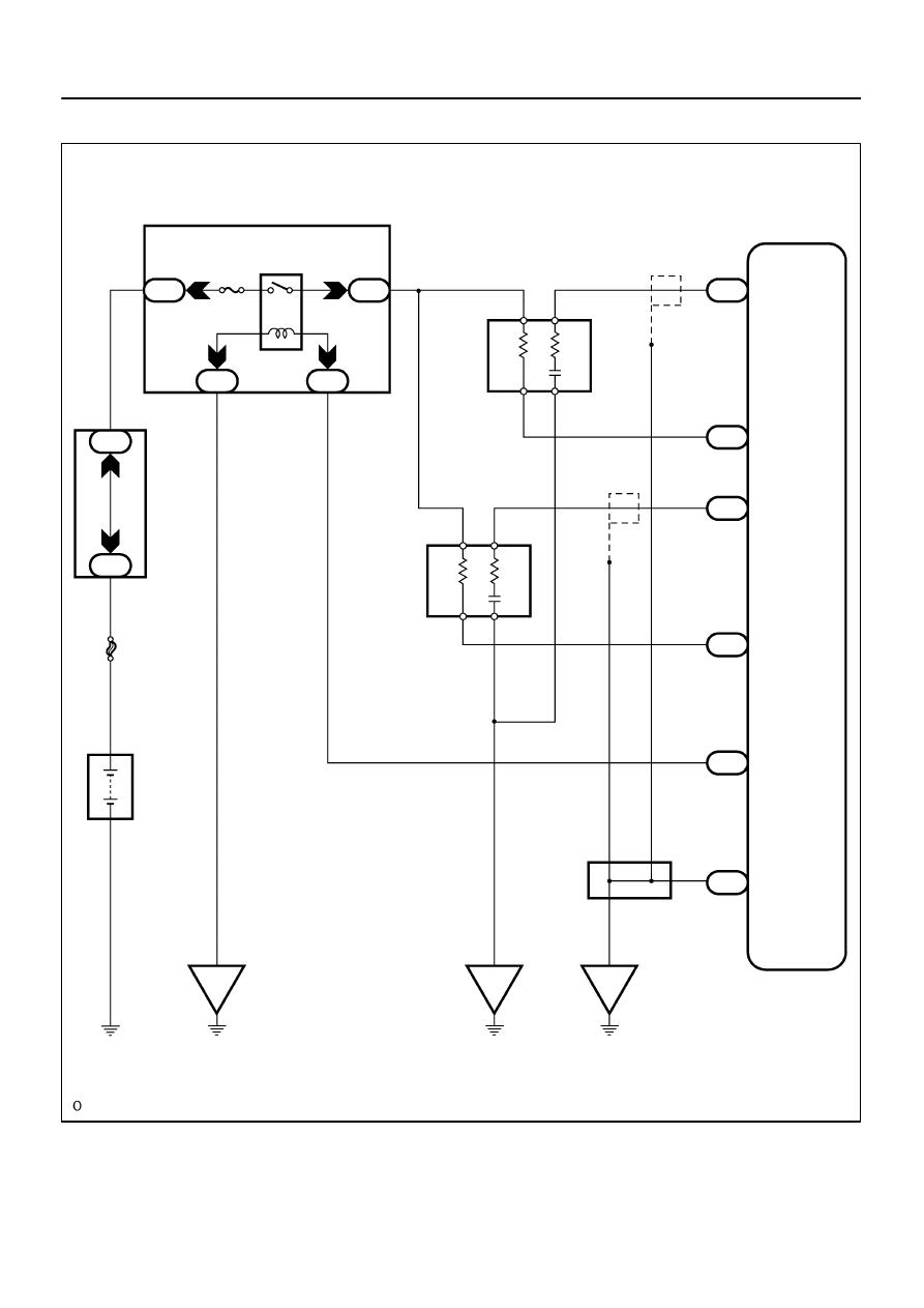
Engine
Room
R/B
21
1
Battery
FL MAIN
B-G
E.F.I.
ECU
Relay
2
1A
1C
1B
1K
E.F.I.
B-W
Heated Oxygen
Sensor (B1S2)
ED
J11 J/C
A
BR
+B
OX
HT
E1
E1
E6
E8
EF
E8
E9
OX1B
HT1B
OX2B
HT2B
MREL
(*1)
ECM
E1
B-G
1
Engine Room J/B
E8
E9
6
29
5
8
1
BR
OX
+B
HT
A
A
(*1)
6
2
1
5
3
2
3
1
4
3
4
2
1
W
L
B
Y
Heated Oxygen
Sensor (B2S2)
W-B
B-W
B-W
*1: Shielded
EF
A
BR
BR
BR
BR
5
3
BR
05-60
-
DIAGNOSTICS
SFI SYSTEM (1MZ-FE)
213
2002 LEXUS ES300 REPAIR MANUAL (RM911U)
WIRING DIAGRAM