Lexus ES300 (2002 year). Service manual - part 75


  Index      Lexus     Lexus ES300 - service and repair manual 2002 year


Search            


Content   ..  73  74  75  76   ..


Lexus ES300 (2002 year). Service manual - part 75


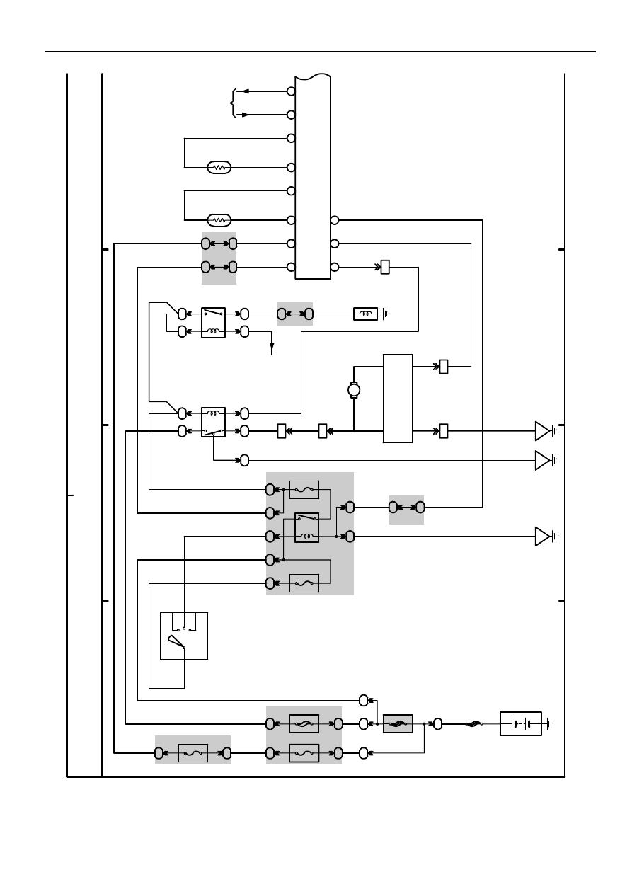
M  OVERALL ELECTRICAL WIRING DIAGRAM

1

2

34

35 

 ES 300

(C

o

nt

.  

n

e

x

t pa

ge

)

B–G

B–G

FL

 M

A

IN

3.

 0W

Ba

tte

ry

1A
2

120A ALT

1D
11

F

1

50A HTR

1A
1

2

1

R

2F
7

10A ECU–B

2M
6

2

AC

C

IG

1

ST

1

AM

1

4

WB

Y

I1

4

Igni

tion S

W

22

A

5A AM1

2E
22

A

8

2

1

3

5

2R
8

72

M

10A HTR

IG1 Relay

2G

24

IA

In

st

ru

m

ent

 P

anel

R

e

in

fo

rc

em

ent

 L

H

W

3

5

2

1

4

11

11

1

11

11

HT

R

Re

la

y

MG

 C

L

T

Re

la

y

L–B

L–B

L–B

B–G

B–G

W

B–G

B–Y

W

L–B

W–B

W–B

W–B

W–B

L–

B

2M
8

3A

55

3A

24

SB

EC

L

e

ft

 F

ender

L–R

L–W

2I

F

3

L–R

1I

J

1

L–R

L–R

3

+B

M

L–R

4

VM

L

B 2

B

low

er

Mo

to

r

12

GN

D

S

I

A1

4

( A

) , A1

5

( B

)

A/

C

 C

o

n

tr

o

As

s

e

m

b

ly

W–B

L–O

3I

J

1

2I

J1

W–B

IE

In

st

ru

m

ent

 P

a

nel

R

e

in

fo

rc

em

ent

 R

H

B 3

Blower Motor
Controller

L–

B

L–O

W–B

2

1

3

5

Y–G

B–W

1J
9

1L
3

B–W

3

A 3

A/C Magnetic
Clutch

D

io

de 

(A/

C

)

<

3

4–2

>

L–W

LG–B

3A

59

3A

29

3A

56

3A

26

W

W

IG

+

B

L–B

W–R

1

2

SG

L–W

TE

LG–B

2

1

SG

5

A17

A/C Room Temp. 
Sensor

B

TR

O

TS

P

V

TS

D

21

Po

w

e

r So

u

rc

e

A

ir

 C

ondi

ti

oni

ng

11

1

1

1

2

30A D. C. C

1

2

B

1

1B

4

0

B

2

3B

3

8

B

2

4B

2

6

B

2

5B

3I

F

7

3B

2B

2

1

B

HR

B

L

W

G

ND

L–O

W–B

A/C Solar Sensor
Automatic Light
Control Sensor<1–12>

L–W

A/C Thermistor

A19

2002

M

5

6

7

8

35  ES 300 (Cont’ d)

A14(A), A15(B)
A/C Control Assembly

7 IG1

V

6 IG1

LG

B

LG
–B

V

1

2

9 IG1

O

8 IG1

B–
Y

B–
Y

O

3

4

10 IG1

P

P

5

AOF

TPO

AOD

S5–1

SG–1

6 IM1

V

7 IM1

LG

B

LG
–B

V

2

1

SG

S5

9 IM1

R–
L

8 IM1

L–
R

L–
R

R–
L

3

4

TPI

MREC

10 IM1

L

L

5

MFRS

AIF

TPI

AIR

S5–2

SG–2

2

1

3

4

5

L–
B

G–
B

B–
R

L–
W

LG

A28

Air Mix Control Servo Motor
(Front Passenger Side)

AMPH

TPP

AMPC

S5–4

SG–4

A ir  C o n d itio n in g

2

1

3

4

5

LG

B

V

L–
R

LG
–R

B–
W

A27

Air Mix Control Servo Motor
(Driver Side)

AMDH

TPD

AMDC

S5–3

SG–3

34 B

10 B

28 B

18 B

17 B

35 B

30 B

9 B

20 B

19 B

36 B

31 B

27 B

14 B

13 B

37 B

32 B

29 B

16 B

15 B

2

1

A

/C

 A

m

bi

ent
 T

e

m

p

.  S

ens

or

A 1

5 A

1 B

16 A

5 B

10 A

8 B

39 B

TELI

SPD

PBEW

RDEF

LP

TAM

SG–6

4 IF7

5 IF7

T

e

lepho

ne C

o

m

p

u

ter

<

2

7

–4>

C

o

m

b

inat
ion M

e

te

r

<

3

3

–3>

S

R

S Sy

ste

m

<

1

2

–7>

R

e

ar

 W
indow

 D

e

fogge

r

S

ys

tem
<

2

6–3

>

L–R

V–
W

G–
R

B–
W

G–
R

B–
W

1 IK1

8 IK1

3 IK1

32 B

33 B

31 B

1 B

23 C

2 A

7 A

6 A

1

4

EB

Right Fender

2 IF5

4 B

PSW

L–
B

D

ual

P

re

ssu

re

 S

W

P 4

L–
B

W

–B

2

1

A

A

3B

129

3B

109

3B

98

3B

118

16 IL1

EF

Intake Side of
Cylinder Block

A

Junction
Connector

J11

A/

C

 L

o

ck

 Se
n

so

r

A 3

A/CS

A/CI

AC1

P–
L

B

Y–
B

BR

BR

W

W–
L

BR

P–
L

B

Y–
B

BR

Engine Control Module

E 7(B), E 8(C)

THR

A/CI

A/CS

HP

LCKI

Air Vent Mode Control Servo Motor

A29

Air Inlet Control Servo Motor

A26

9 IK1

4 A

TW

Y–
G

Y

G

E

n

gi

ne C

ont
ro

l

M

odul

e<
4–1

4>

(*1)
(*2)

(*1)
(*2)

* 1 : w/ VSC
* 2  :  w/o  VSC

M

M

44 3B

24 3B

33 3B

13 3B

34 3B

14 3B

(*1)

(*2)

(*1)
(*2)

V

E

n

gi

ne
 C

o

n

tro

l

M

o

d

u

le<
4–
5>

V

T

hef
t D

e

te

rr

ent

E

C

U

<

1–1

5>

V

4 IK1

V

VZ

M

GND

PT

DEF

FACE

APPENDIX

AP-2

5

10

15

20

25

30

35

40

45

50

55

60

65

70

Area

Item

Major Dimension & 

V

ehicle 

W

eights

Performance

Engine

Engine

Electric

Chassis

MAJOR TECHNICAL SPECIFICATIONS

U.S.A. and CANADA

Body Type

4-Door Sedan

Vehicle Grade

Model Code

MCV30L-BEAGKA

Length

mm (in.)

4855 (191.1)

Overall

Width

mm (in.)

1810 (71.3)

Overall

Height

mm (in.)

1455 (57.3)

Wheel Base

mm (in.)

2720 (107.1)

Tread

Front

mm (in.)

1545 (60.8)

Tread

Rear

mm (in.)

1535 (60.4)

Effective Head Room

Front

mm (in.)

978 (38.5)

Effective Head Room

Rear

mm (in.)

950 (37.4)

Effective Leg Room

Front

mm (in.)

1072 (42.2)

Effective Leg Room

Rear

mm (in.)

904 (35.6)

Shoulder Room

Front

mm (in.)

1443 (56.8)

Shoulder Room

Rear

mm (in.)

1417 (55.8)

Overhang

Front

mm (in.)

995 (39.2)

Overhang

Rear

mm (in.)

1140 (44.9)

Min. Running Ground Clearance

mm (in.)

155 (6.1)

Angle of Approach

degrees

15.9

Angle of Departure

degrees

16.3

Front

kg (lb)

955 (2110)

Curb Mass.

Rear

kg (lb)

605 (1330)

Curb Mass.

Total

kg (lb)

1560 (3440)

Front

kg (lb)

1085 (2390)

Gross Vehicle Mass.

Rear

kg (lb)

940 (2075)

Gross Vehicle Mass.

Total

kg (lb)

2025 (4465)

Fuel Tank Capacity

L (U.S. gal., lmp.gal.)

70 (18.5, 15.4)

Luggage Compartment Capacity

m

3

 (cu.ft.)

0.519 (18.3)

Max. Speed

km/h (mph)

220 (137)

Max. Cruising Speed

km/h (mph)

Acceleration

0 to 60 mph

sec.

8.1

Acceleration

0 to 400 m

sec.

16.1

1st Gear km/h (mph)

52 (32)

Max. Permissible

2nd Gear km/h (mph)

94 (58)

Max. Permissible
Speed

3rd Gear km/h (mph)

147 (91)

p

4th Gear km/h (mph)

Turning Diameter

Wall to Wall

m (ft.)

6.0 (19.7)

Turning Diameter
(Outside Front)

Curb to Curb

m (ft.)

5.6 (18.4)

Engine Type

1MZ-FE

Valve Mechanism

24-Valve, DOHC

Bore 

 Stroke

mm (in.)

87.5 

 83.0 (3.44  3.27)

Displacement

cm

3

 (cu.in.)

2995 (182.8)

Compression Ratio

10.5 : 1

Carburetor Type

SFI

Research Octane No.

RON

96

Max. Output (SAE-NET)

kW/rpm (HP@rpm)

156/5800 (210@5800)

Max. Torque (SAE-NET) N

·

m/rpm (lb-ft@rpm)

298/4400 (220@4400)

Battery Capacity (5HR)

Voltage & Amp. hr.

12 – 55

Alternator Output

Watts

1200

Starter Output

kW

1.6

Clutch Type

Transaxle Type

U150E

In First

3.938

In Second

2.194

Transmission Gear

In Third

1.411

Transmission Gear
Ratio*

In Fourth

0.973

In Fifth

0.703

In Reverse

3.141

Counter Gear Ratio

1.019

Differential Gear Ratio (Final)

3.478

Brake Type

Front

Ventilated Disc

Brake Type

Rear

Solid Disc

Parking Brake Type

Drum

Brake Booster Type and Size

in.

Single 10.5”

Proportioning Valve Type

Suspension Type

Front

MacPherson Strut

Suspension Type

Rear

MacPherson Strut

Stabilizer Bar

Front

STD

Stabilizer Bar

Rear

STD

Steering Gear Type

Rack & Pinion

Steering Gear Ratio (Overall)

16.0

Power Steering Type

Integral Type

*: Counter Gear Ratio Included

  2001 

TOYOTA   MOTOR  CORPORATION

All rights reserved. This book may not be repro-
duced or copied, in whole or in part, without the
written permission of Toyota Motor Corporation.
First Printing: Jul. 23, 2001 01-010723-00

FOREWORD

To assist you in your service activities, this manual explains the main characteristics of the 2002 model year
vehicles, in particular providing a technical explanation of the construction and operation of new mecha-
nisms and new technology used.

CAUTION, NOTICE, REFERENCE and NOTE are used in the following ways:

CAUTION

A potentially hazardous situation which could result in injury to people may occur
if instructions on what to do or not do are ignored.

NOTICE

Damage to the vehicle or components may occur if instructions on what to do or not
do are ignored.

REFERENCE

Explains the theory behind mechanisms and techniques.

NOTE

Notes or comments not included under the above 3 titles.

All information contained herein is the most up-to-date at the time of publication. We reserve the right to make
changes without prior notice.


Content   ..  73  74  75  76   ..