Lexus ES300 (1997 year). Service manual - part 140
Z05935
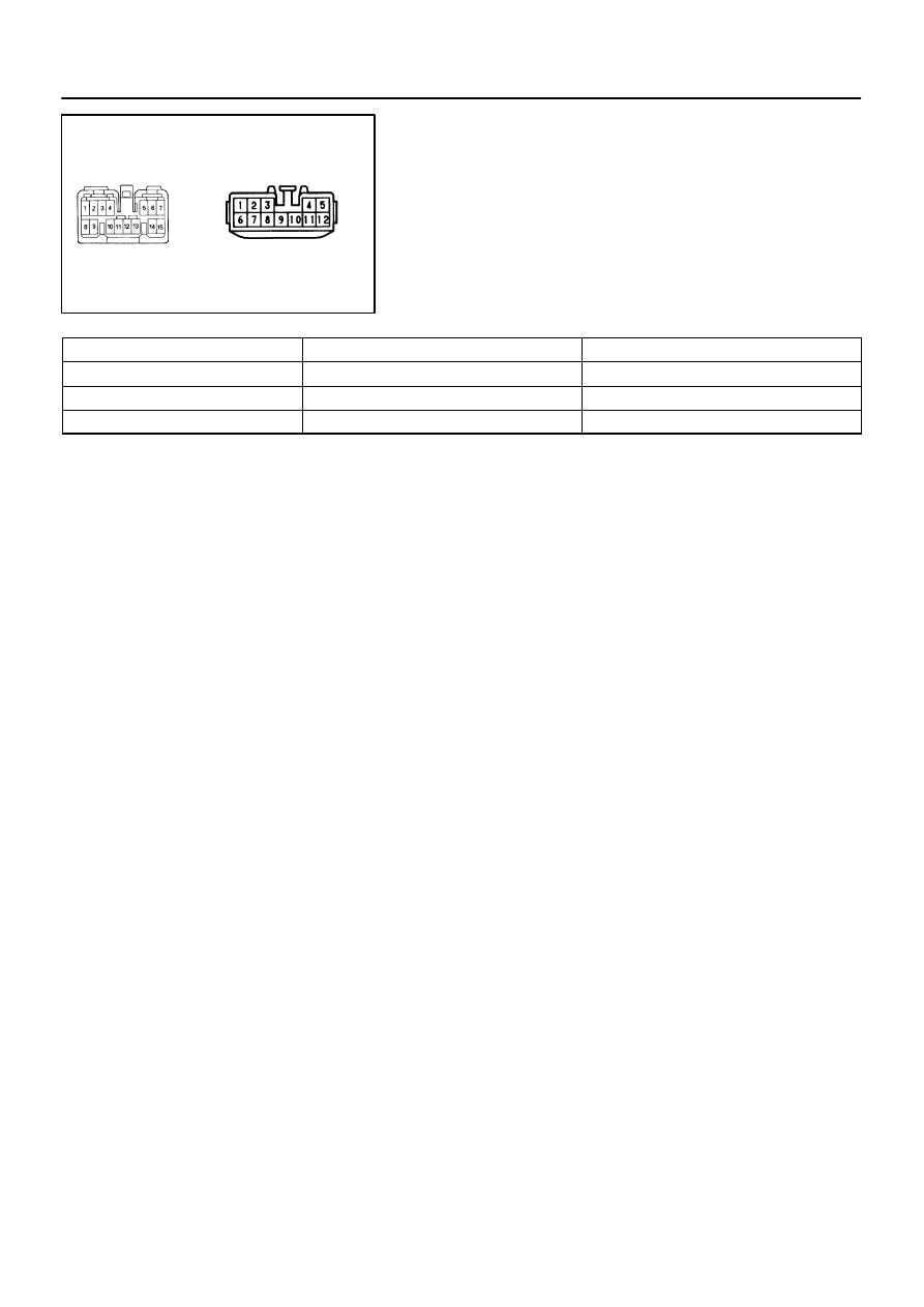
Wire Harness Side
Connector ”A”
Connector ”B”
BE6542 e–12–1
BE–166
–
BODY ELECTRICAL
AUDIO SYSTEM
1550
1997 LEXUS ES300 (RM511U)
3.
INSPECT RADIO RECEIVER ASSEMBLY CIRCUIT
Disconnect the connectors from the radio receiver assembly,
and inspect the connector on the wire harness side.
Tester connection
Condition
Specified condition
A4 – Ground
Constant
Battery positive voltage
A3 – Ground
Ignition switch LOCK
No voltage
A3 – Ground
Ignition switch ACC or ON
Battery positive voltage
If the circuit is not as specified, inspect the circuits connected
to other parts.
HINT:
Check the wire harness between radio receiver assembly and
the CD auto changer, between radio receiver assembly and
power amplifier.
4.
INSPECT GLASS IN PRINTED ANTENNA
(Use same procedure as for ”INSPECT DEFOGGER WIRES”
on page BE–126.)
5.
REPAIR GLASS PRINTED ANTENNA
(Use same procedure as for ”REPAIR DEFOGGER WIRES” on
page BE–127.)