Lexus GS300/400 (2000 year). Service manual - part 250
RS07R–01
H02574
RS–54
–
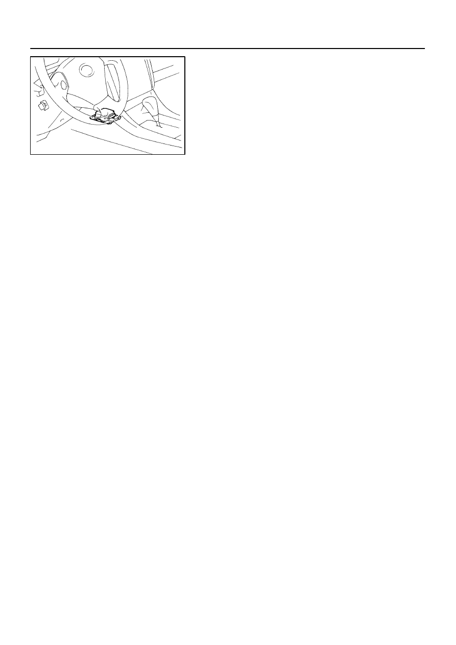
SUPPLEMENTAL RESTRAINT SYSTEM
AIRBAG SENSOR ASSEMBLY
2285
INSPECTION
1.
VEHICLE NOT INVOLVED IN COLLISION
Do a diagnostic system check.
(See page
2.
VEHICLE INVOLVED IN COLLISION AND AIRBAG IS
NOT DEPLOYED
Do a diagnostic system check.
(See page
3.
VEHICLE INVOLVED IN COLLISION AND AIRBAG IS
DEPLOYED
Replace the airbag sensor assembly.