Lexus GS300/400 (2000 year). Service manual - part 210


  Index      Lexus     Lexus GS300/400 - service and repair manual 2000 year


Search            


Content   ..  208  209  210  211   ..


Lexus GS300/400 (2000 year). Service manual - part 210


B09507

B01620

Ohmmeter 3 (CL–)

4 (CL+)

1 (M+)

2 (M–)

B01942

VC

Ohmmeter

E2

B01943

VC

Ohmmeter

E2

SFI (2JZ–GE)

THROTTLE BODY

SF–33

1499

(2)

Turn the A/C switch ON and OFF, and check the idle
speed.

Idle speed (Transmission in neutral):
700 

±

 50 rpm (A/C OFF)

750 

±

 50 rpm (A/C ON)

NOTICE:
Perform inspection under condition without electrical load.

(3)

With engine idling, pinch the air assist hose and
check that engine speed drops, and then returns
back up to idle speed.

If operation is not as specified, check the throttle body, wiring
and ECM.
(f)

After checking the above (b) to (e), perform the diving test
and check that there is no sense of incongruity.
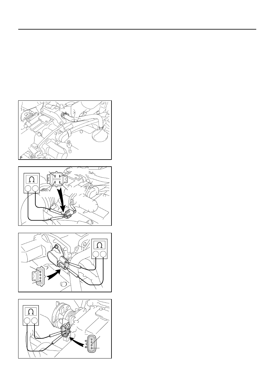
3.

INSPECT THROTTLE CONTROL MOTOR

(a)

Disconnect the throttle control motor connector.

(b)

Using an ohmmeter, measure the resistance between ter-
minal 3 (CL–) and 4 (CL+).
Resistance: 4.2 – 5.2 

 at 20

°

C (68

°

F)

(c)

Using an ohmmeter, measure the resistance between ter-
minal 1 (M+) and 2 (M–).
Resistance: 0.3 – 100 

 at 20

°

C (68

°

F)

If the resistance is not as specified, replace the throttle control
motor. (See page 

SF–37

)

(d)

Reconnect the throttle control motor connector.

4.

INSPECT THROTTLE POSITION SENSOR

(a)

Disconnect the throttle position sensor connector.

(b)

Using an ohmmeter, measure the resistance between ter-
minals VC and E2.
Resistance: 1.2 – 3.2 k

 at 20

°

C (68

°

F)

If the resistance is not as specified, replace the throttle position
sensor. (See page 

SF–37

)

(c)

Reconnect the throttle position sensor connector.

5.

INSPECT ACCELERATOR PEDAL POSITION SEN-
SOR

(a)

Disconnect the accelerator pedal position sensor con-
nector.

(b)

Using an ohmmeter, measure the resistance between ter-
minals VC and E2.
Resistance: 1.2 – 3.2 k

 at 20

°

C (68

°

F)

If the resistance is not as specified, replace the accelerator ped-
al position sensor. (See page 

SF–37

)

SF–34

SFI (2JZ–GE)

THROTTLE BODY

1500

(c)

Reconnect the accelerator pedal position sensor connec-
tor.

6.

REINSTALL ENGINE COVER

Reinstall the engine cover with the 4 nuts.

SF0NM–07

B09000

Intake Air Resonator

PCV Hose

PS Air Hose

Throttle Control
Motor Connector

Throttle Body Bracket

Throttle Position Sensor Connector

Water Bypass Hose

Water Bypass Hose

Engine Wire Clamp

Accelerator Pedal Position
Sensor Connector

Accelerator Cable

21 (210, 15)

N·m (kgf·cm, ft·lbf) : Specified torque

Throttle Body

Engine Cover

B01947

Cover

Accelerator Pedal Position Sensor

Washer Plate

Throttle Control Motor

Throttle Position Sensor

Bracket

x 5

SFI (2JZ–GE)

THROTTLE BODY

SF–35

1501

COMPONENTS

SF0NN–05

B01615

B01616

Forward

Down–Side
Diagonal

(2)

(1)

SF–36

SFI (2JZ–GE)

THROTTLE BODY

1502

REMOVAL

1.

DRAIN ENGINE COOLANT

2.

REMOVE ENGINE COVER

Remove the 4 nuts and engine cover.
3.

REMOVE INTAKE AIR RESONATOR

4.

REMOVE THROTTLE BODY BRACKET AND
THROTTLE BODY

(a)

Disconnect the accelerator cable.

(b)

Disconnect the throttle position sensor connector.

(c)

Disconnect the throttle control motor connector.

(d)

Disconnect the accelerator pedal position sensor con-
nector.

(e)

Disconnect the engine wire clamp from the clamp bracket
of throttle body.

(f)

Remove the 2 bolts and nut holding the throttle body to
the intake air connector.
Torque: 21 N·m (210 kgf·cm, 15 ft·lbf)

(g)

Remove the 4 nuts and throttle body bracket.
Torque: 21 N·m (210 kgf·cm, 15 ft·lbf)

(h)

Slightly slide the throttle body away from the intake air
connector.

NOTICE:
When putting up the throttle body, do not hold the motor
part.
(i)

Disconnect the 2 water bypass hoses from the throttle
body, and remove the throttle body.

HINT:


At the time of installation, please refer to the following
items.


Connect the water bypass hose with its discrimination
mark downward.


Install the with its craw direction for (1) forward and down–
side diagonal (engine side about 45

°

) for (2).


Content   ..  208  209  210  211   ..