Lexus GS300/400 (2000 year). Service manual - part 124
CO09Z–03
A02725
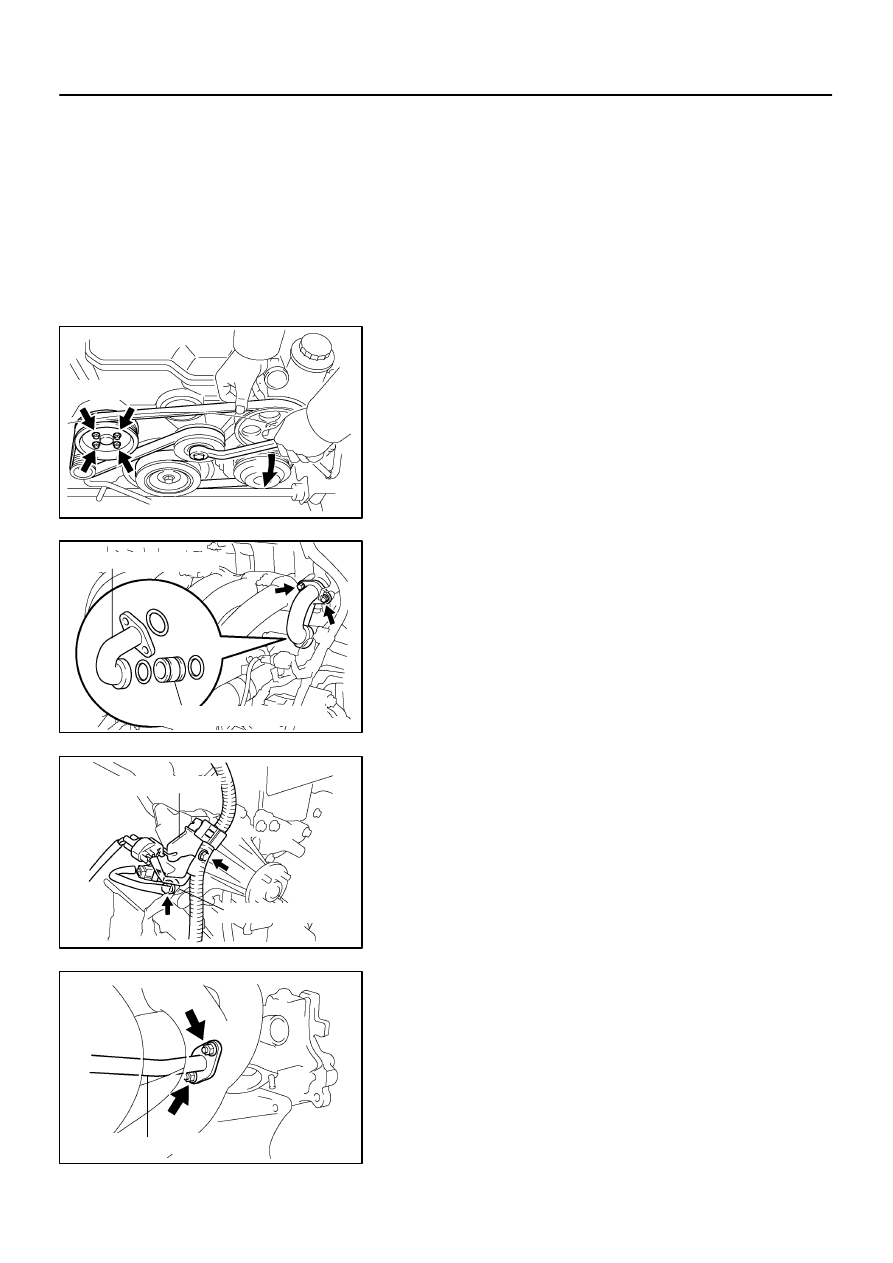
Turn
Loosen
B01614
Water Bypass Outlet
No.1 Water Bypass Hose
B01638
Clamp Bracket
Connector Bracket
B01572
No.2 Water Bypass Pipe
–
COOLING (2JZ–GE)
WATER PUMP
CO–5
1543
REMOVAL
1.
REMOVE RADIATOR ASSEMBLY
(See page
2.
REMOVE DRIVE BELT AND WATER PUMP PULLEY
(a)
Loosen the 4 nuts holding the water pump pulley to the
water pump.
(b)
Loosen the drive belt tension by turning the drive belt ten-
sioner clockwise, and remove the drive belt.
(c)
Remove the 4 nuts and water pump pulley.
3.
REMOVE TIMING BELT AND IDLER PULLEY
(See page
4.
REMOVE WATER BYPASS OUTLET AND NO.1
WATER BYPASS PIPE
(a)
Remove the 2 bolts, water bypass outlet and No.1 water
bypass pipe.
(b)
Remove the 3 O–rings from the water bypass outlet and
No.1 water bypass pipe.
5.
REMOVE WATER INLET AND THERMOSTAT
(See page
6.
REMOVE WATER PUMP
(a)
Loosen the nut and remove the bolt, slide the generator
away from the water pump.
(b)
Remove the bolt, and disconnect the clamp bracket (for
engine wire).
(c)
Remove the bolt, and disconnect the connector bracket
(for crankshaft position sensor connector).
(d)
Remove the 2 nuts, and disconnect the No.2 water by-
pass pipe from the water pump.