Lexus GS300/400 (2000 year). Service manual - part 115
CH044–01
B01996
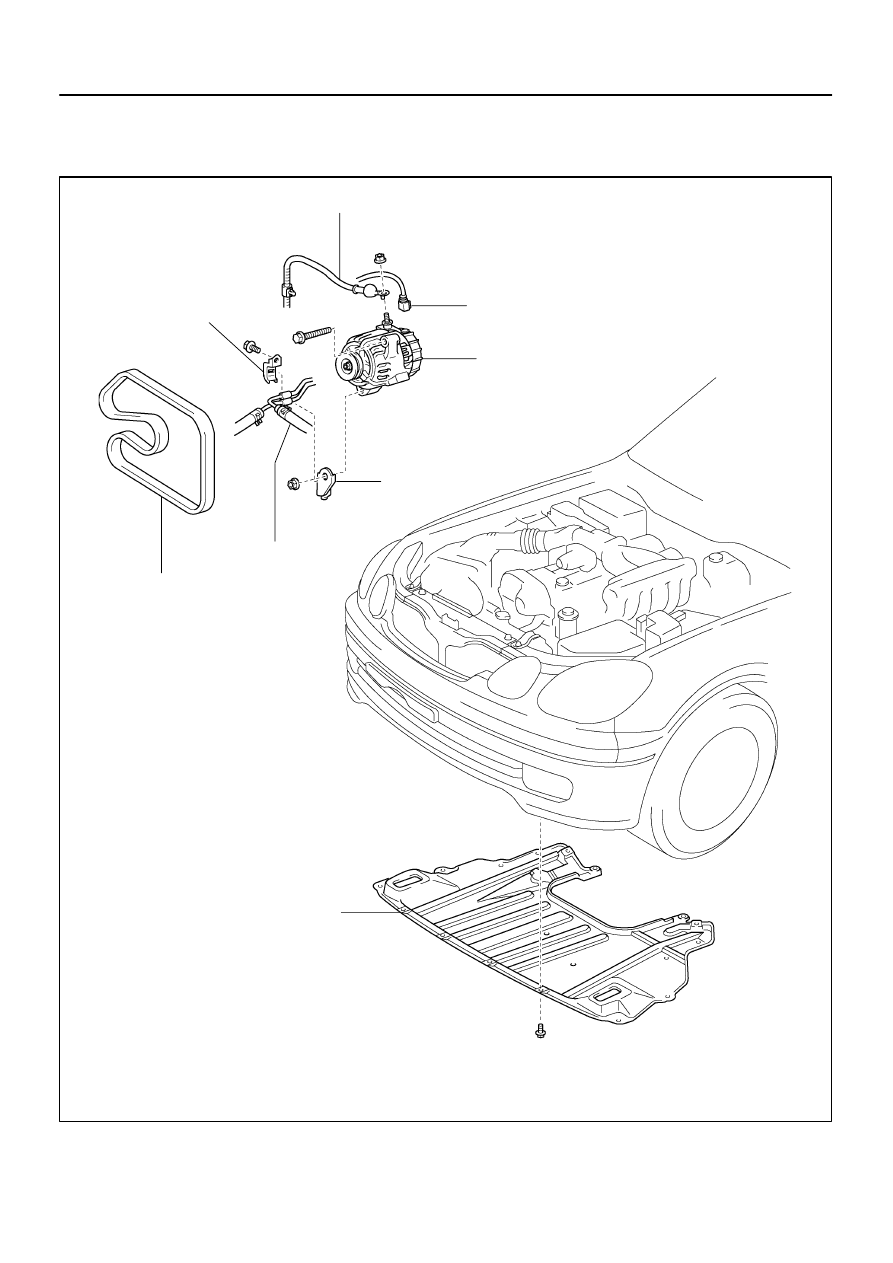
Generator Wire
Pipe Clamp
A/T Oil Cooler Pipe
Pipe Bracket
Generator Connector
Generator
Engine Under Cover
x 18
Drive Belt
CH–4
–
CHARGING (2JZ–GE)
GENERATOR
1606
GENERATOR
COMPONENTS