Lexus GS300/400 (2000 year). Service manual - part 97
I04105
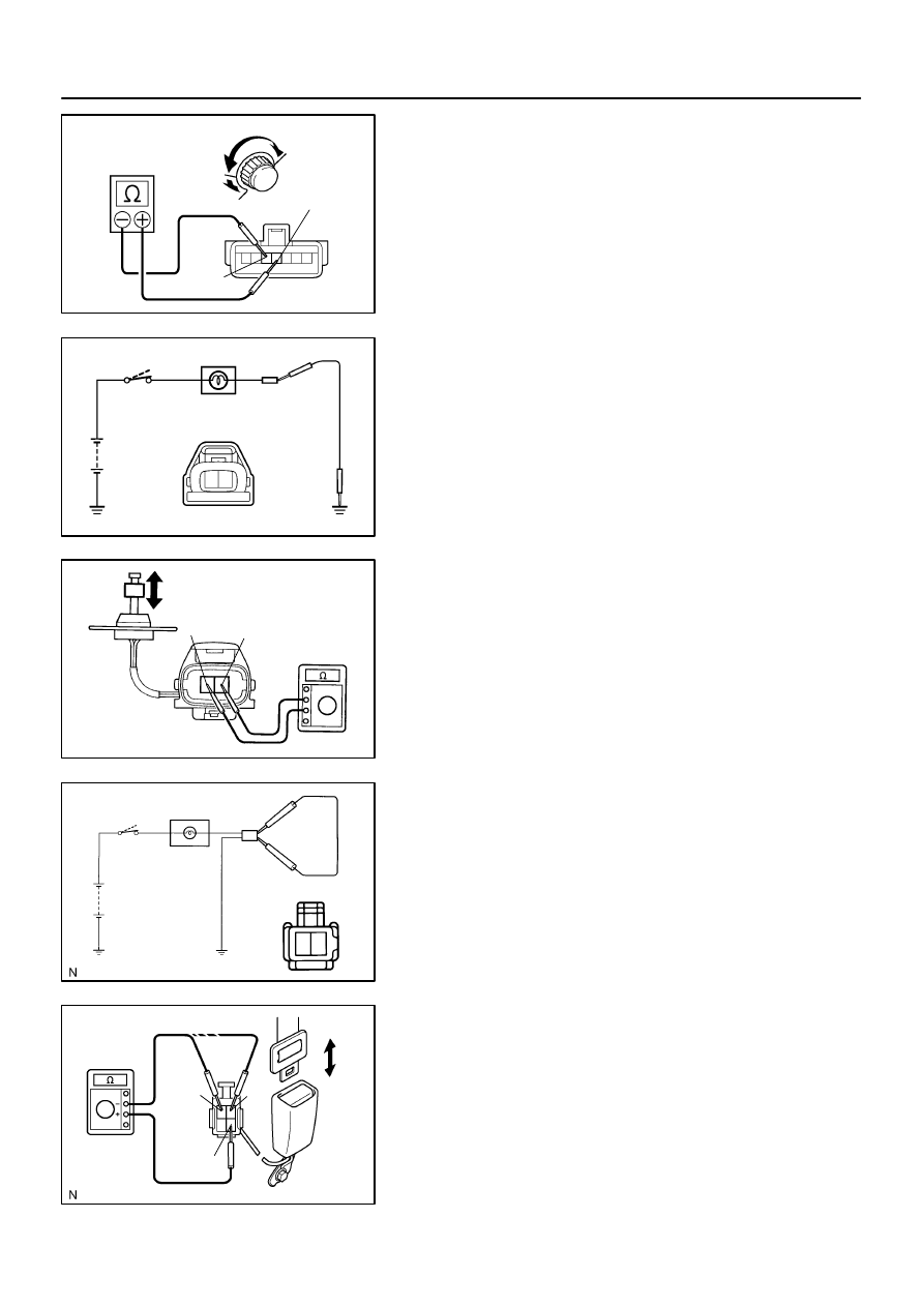
Dark
(10k
Ω
)
Bright
(0
Ω
)
4
5
I01322
Battery
Ignition
Switch
Warning Light
2
1
Wire Harness Side
I01323
1
2
OFF
ON
I01328
Battery
Ignition
Switch
Warning Light
2
1
Wire Harness Side
I04107
1
2
4
OFF
ON
BE–102
–
BODY ELECTRICAL
COMBINATION METER
2403
30.
INSPECT LIGHT CONTROL RHEOSTAT OPERATION
Gradually, turn the rheostat knob from the bright side to dark
side and check that the resistance decreases from 10 k
Ω
to 0
Ω
between terminal 4 and 5. (Rheostat knob turned to clock-
wise)
If operation is not as specified, replace the rheostat light control.
31.
INSPECT WINDOW WASHER LEVEL WARNING
LIGHT
(a)
Disconnect the connector from the warning switch and
ground terminal on the wire harness side connector.
(b)
Engine running and check that the warning light lights up.
If the warning light does not light up, inspect the bulb or wire har-
ness.
32.
INSPECT WINDOW WASHER LEVEL WARNING
SWITCH CONTINUITY
(a)
Check that no continuity exists between the terminals with
the switch OFF (float up).
(b)
Check that continuity exists between the terminals with
the switch ON (float down).
If operation is not as specified, replace the switch or inspect
ground point.
33.
INSPECT SEAT BELT WARNING LIGHT
(a)
Disconnect the connector from the retractor switch and
ground terminal on the wire harness side connector.
(b)
Turn the ignition switch ON and check that the warning
light lights up.
If the warning light does not light up, inspect the bulb or wire har-
ness.
34.
INSPECT SEAT BELT BUCKLE SWITCH CONTINUITY
(a)
Check that continuity exists between the terminals 1 and
4 on the switch side connector with the switch ON (belt
fastened).
(b)
Check that continuity exists between the terminals 2 and
4 on the switch side connector with the switch OFF (belt
unfastened).
If operation is not as specified, replace the switch.