Lexus GS300/400 (2000 year). Service manual - part 40
I04131
3
within
60 seconds
1
I05102
1
2
4
5
I05103
1
2
4
5
I05104
1
2
4
5
I05105
1
2
4
5
–
BODY ELECTRICAL
POWER WINDOW CONTROL SYSTEM
BE–123
2424
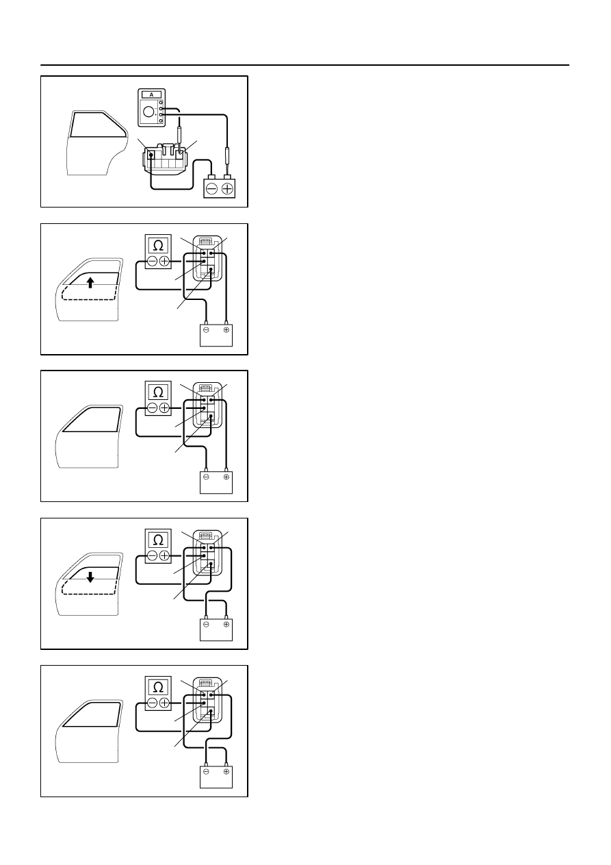
(d)
Reverse the polarity, check that the window begins to de-
scend within approximately 60 seconds.
If operation is not as specified, replace the motor.
19.
Driver’s door (window up):
INSPECT JAM PROTECTION LIMIT SWITCH OPERA-
TION
(a)
Connect the positive (+) lead from the ohmmeter to termi-
nal 4 and the negative (–) lead to terminal 5.
(b)
Connect the positive (+) lead from the battery to terminal
1 and the negative (–) lead to terminal 2.
(c)
Check that the continuity exists when the window goes
up.
(d)
Check that the no continuity exists when the window is in
the fully closed position.
If operation is not as specified, replace the motor.
NOTICE:
If connecting the wire harness wrongly, the sensor might
be damaged so caution is necessary.
20.
Driver’s door (window down):
INSPECT JAM PROTECTION LIMIT SWITCH OPERA-
TION
(a)
Connect the positive (+) lead from the ohmmeter to termi-
nal 4 and the negative (–) lead to terminal 5.
(b)
Connect the positive (+) lead from the battery to terminal
2 and the negative (–) lead to terminal 1.
(c)
Check that the continuity exists when the window goes
down.
(d)
Check that the no continuity exists when the window is in
the fully opened position.
If operation is not as specified, replace the motor.
NOTICE:
If connecting the wire harness wrongly, the sensor might
be damaged so caution is necessary.
21.
Driver’s Door:
INSPECT JAM PROTECTION LIMIT SWITCH CIRCUIT
(See page