Lexus GS300/400 (2000 year). Service manual - part 11
N20013
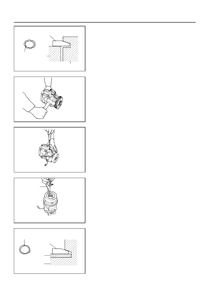
R–Shape
Rotor
Snap Ring
Compressor
AC1743
AC1744
AC0950
SST
N20012
R–Shape
Snap Ring
Compressor
Stator
–
AIR CONDITIONING
COMPRESSOR AND MAGNETIC CLUTCH
AC–41
2726
NOTICE:
At the time of reassembly, please refer to the following
item.
The snap ring should be installed so that beveled side
faces up.
(b)
Using a plastic hammer, tap the rotor off the shaft.
NOTICE:
Be careful not to damage the pulley when tapping on the ro-
tor.
3.
REMOVE STATOR
(a)
Disconnect the stator lead wire from the compressor
housing.
(b)
Using SST, remove the snap ring.
SST
07114–84020
NOTICE:
At the time of reassembly, please refer to the following
item.
The snap ring should be installed so that its beveled side
faces up.