Jaguar XJ (X350). Service manual - part 1282


  Index      Jaguar     Jaguar XJ (X350) - service and repair manual 2003-2009 year


Search            


Content   ..  1280  1281  1282  1283   ..


Jaguar XJ (X350). Service manual - part 1282


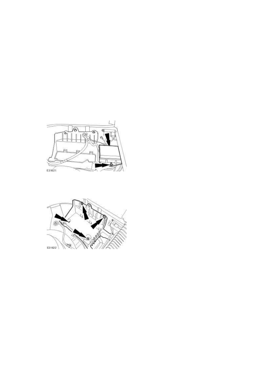
Battery Tray (86.15.11)   

Removal  


1 . Remove the battery.  

For additional information, refer to Battery (86.15.01)  


2 . Remove the spare wheel and tire. 


3 . Detach the rear power distribution box.  


4 . Remove the battery tray.  


Installation  


1 . To install, reverse the removal procedure. 


1) Tighten to 13 Nm.


www.

414-02 : Generator and Regulator


Specifications


Specifications  

Torque Specifications  

Description  

Nm  lb-ft  lb-in 

Generator retaining bolts - vehicles fitted with 3.0L engine  

48   35   -  

Generator upper retaining bolt - vehicles fitted with 3.5 or 4.2L engine  21   15   -  

Generator lower retaining bolt - vehicles fitted with 3.5 or 4.2L engine  40   30   -  

Generator retaining bolts - vehicles fitted with 2.7L Diesel engine  

47   35   -  

Battery positive cable retaining nut  

12   9  

-  


Description and operation


Generator   

The generator is belt driven by the accessory drive belt. For additional information, refer to  

Accessory Drive (303-05) 

When the engine is started, the generator begins to generate alternating current (AC) which is 

converted to direct current (DC) internally. The DC current and voltage is controlled by the voltage 

regulator, (located inside the generator) and then supplied to the battery through the main battery 

positive cable. 


The 3.0L generator is solidly mounted to the engine, while the 3.5L and 4.2L generator is pivot 

mounted. The 2.7L Diesel generator is also solidly mounted to the engine. The generators are driven 

at approximately three times engine speed. 

Vehicles fitted with 3.0L engine (L3B generator) 

The engine control module (ECM) can switch the voltage regulator between two voltages to optimize 

the charging of the battery. 


The low voltage regulator setting is 13.6 volts and the high voltage regulator setting 15.3 volts, 

measured with the generator at 25°C (77°F) and charging at a rate of 5 amps. These values decrease 

with a rise in temperature or current flow. 


The ECM determines the output voltage setting of the generator. The high voltage setting is always 

selected by the ECM once the vehicle has started. The ECM determines the period of time that the 

high voltage setting is selected for. 


There are three different time periods selected by the ECM which is dependent upon the vehicle 

conditions when the vehicle is started: 


The longest period of time is selected if the ECM determines that the vehicle has been 
'soaking' for sufficient time to allow the engine coolant temperature (ECT) and the air intake 
temperature (IAT) to fall within 6°C (43°F) of each other.  


The intermediate time period is selected when the ECT and the IAT are below 15°C (59°F).  


The shortest time period is the default time and is used to provide a short period of boost 
charge.  

At the end of these time periods the voltage is always set to the low voltage setting to prevent the 

battery from being over charged. 


The time periods are variable depending upon the temperature and battery voltage. The target 

voltage of the battery varies between 14 volts and 15 volts depending upon the ambient 

temperature and the vehicle operating conditions. Once this target voltage has been achieved, 

www.


Content   ..  1280  1281  1282  1283   ..