Isuzu Trooper (1998-2002 year). Service manual - part 539


  Index      Isuzu     Isuzu Trooper - service and repair manual 1998-2002 year


Search            


Content   ..  537  538  539  540   ..


Isuzu Trooper (1998-2002 year). Service manual - part 539


6E–526

6VE1 3.5 ENGINE DRIVEABILITY AND EMISSIONS

General Description (Fuel Metering)

Acceleration Mode

The PCM provides extra fuel when it detects a rapid
increase in the throttle position and the air flow.

Battery Voltage Correction Mode

When battery voltage is low, the PCM will compensate for
the weak spark by increasing the following:

D

The amount of fuel delivered.

D

The idle RPM.

D

Ignition dwell time.

Clear Flood Mode

Clear a flooded engine by pushing the accelerator pedal
down all the way.  The PCM then de-energizes the fuel
injectors.  The PCM holds the fuel injectors de-energized
as long as the throttle remains above 80% and the engine
speed is below 800 RPM.  If the throttle position becomes
less than 80%, the PCM again begins to pulse the
injectors “ON” and “OFF,” allowing fuel into the cylinders.

Deceleration Mode

The PCM reduces the amount of fuel injected when it
detects a decrease in the throttle position and the air flow.
When deceleration is very fast, the PCM may cut off fuel
completely for short periods.

Engine Speed/Vehicle Speed/Fuel Disable
Mode

The PCM monitors engine speed.  It turns off the fuel
injectors when the engine speed increases above 6400
RPM. The fuel injectors are turned back on when engine
speed decreases below 6150 RPM.

Fuel Cutoff Mode

No fuel is delivered by the fuel injectors when the ignition
is “OFF.”  This prevents engine run-on.  In addition, the
PCM suspends fuel delivery if no reference pulses are
detected (engine not running) to prevent engine flooding.
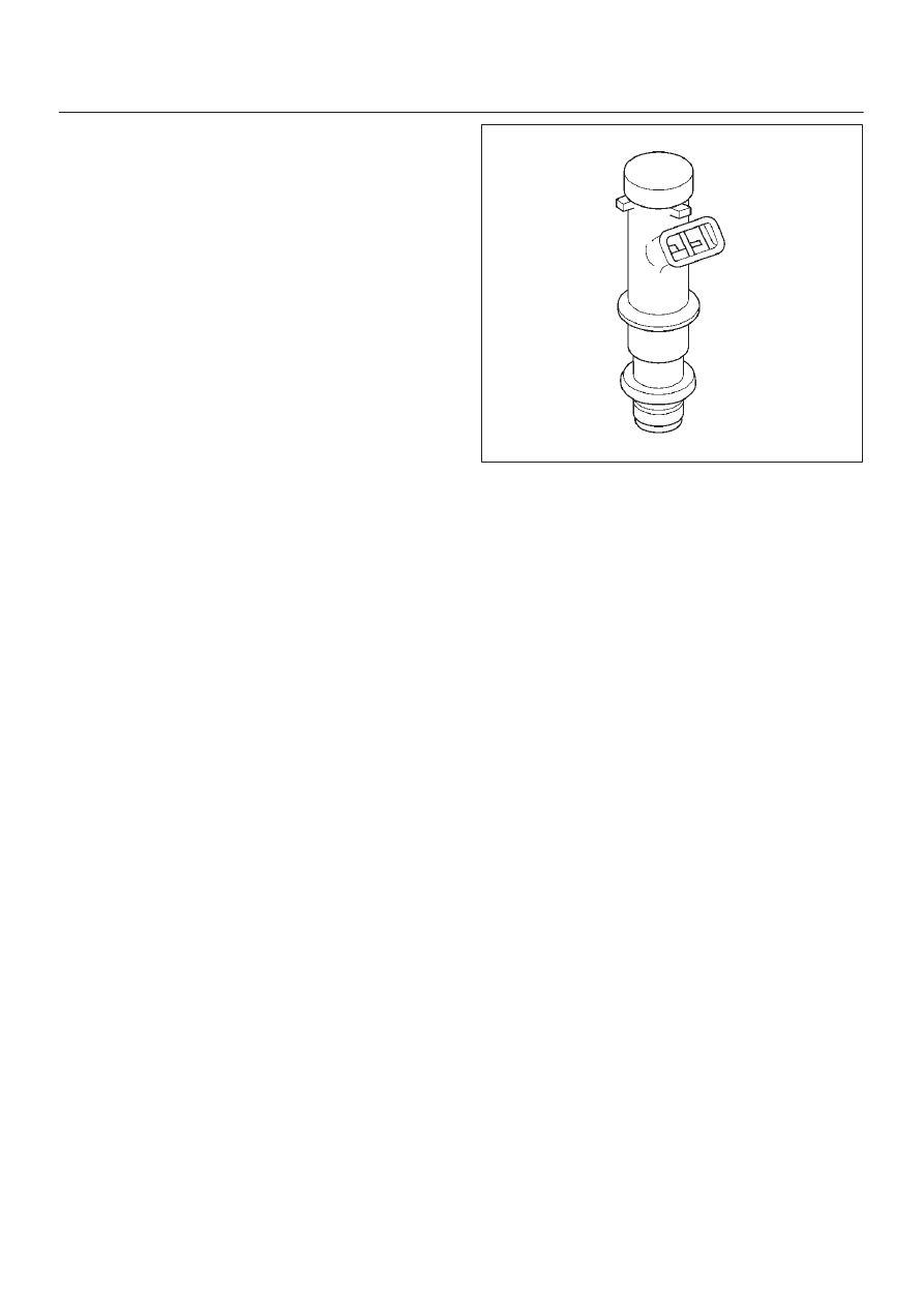
Fuel Injector

The sequential multiport fuel injection (SFI) fuel injector is
a solenoid-operated device controlled by the PCM. The
PCM energizes the solenoid, which opens a valve to allow
fuel delivery.
The fuel is injected under pressure in a conical spray
pattern at the opening of the intake valve. Excess fuel not
used by the injectors passes through the fuel pressure
regulator before being returned to the fuel tank.
A fuel injector which is stuck partly open will cause a loss
of fuel pressure after engine shut down, causing long
crank times.

014RY00009

Fuel Metering System Components

The fuel metering system is made up of the following
parts:

D

The fuel injectors.

D

The throttle body.

D

The fuel rail.

D

The fuel pressure regulator.

D

The PCM.

D

The crankshaft position (CKP) sensor.

D

The ION sensing module.

D

The fuel pump.

D

The fuel pump relay.

Basic System Operation
The fuel metering system starts with the fuel in the fuel
tank.  An electric fuel pump, located in the fuel tank,
pumps fuel to the fuel rail through an in-line fuel filter.  The
pump is designed to provide fuel at a pressure above the
pressure needed by the injectors.  A fuel pressure
regulator in the fuel rail keeps fuel available to the fuel
injectors at a constant pressure.  A return line delivers
unused fuel back to the fuel tank.  Refer to 

Section 6C for

further information on the fuel tank, line filter, and fuel
pipes.

Fuel Metering System Purpose

The basic function of the air/fuel metering system is to
control the air/fuel delivery to the engine.  Fuel is delivered
to the engine by individual fuel injectors mounted in the
intake manifold near each intake valve.
The main control sensor is the heated oxygen sensor
(HO2S) located in the exhaust system.  The HO2S tells
the PCM how much oxygen is in the exhaust gas.  The
PCM changes the air/fuel ratio to the engine by controlling
the amount of time that fuel injector is “ON.”  The best
mixture to minimize exhaust emissions is 14.7 parts of air
to 1 part of gasoline by weight, which allows the catalytic
converter to operate most efficiently.  Because of the
constant measuring and adjusting of the air/fuel ratio, the
fuel injection system is called a “closed loop” system.

6E–527

6VE1 3.5L ENGINE DRIVEABILITY AND EMISSIONS

The PCM monitors signals from several sensors in order
to determine the fuel needs of the engine. Fuel is
delivered under one of several conditions called “modes.”
All modes are controlled by the PCM.

Fuel Pressure Regulator

The fuel pressure regulator is a diaphragm-operated
relief valve mounted on the fuel rail with fuel pump
pressure on one side and manifold pressure on the other
side.  The fuel pressure regulator maintains the fuel
pressure available to the injector at three times
barometric pressure adjusted for engine load.  It may be
serviced separtely.
If the pressure is too low, poor performance and a DTC
P0131, DTC P0151,DTC P0171 or DTC P1171 will be the
result.  If the pressure is too high, excessive odor and/or a
DTC P0132, DTC P0152,DTC P0172 will be the result.
Refer to 

Fuel System Diagnosis for information on

diagnosing fuel pressure conditions.

014RY00010

Fuel Pump Electrical Circuit

When the key is first turned “ON,” the PCM energizes the
fuel pump relay for two seconds to build up the fuel
pressure quickly.  If the engine is not started within two
seconds, the PCM shuts the fuel pump off and waits until
the engine is cranked.  When the engine is cranked and
the 58 X crankshaft position signal has been detected by
the PCM, the PCM supplies 12 volts to the fuel pump relay
to energize the electric in-tank fuel pump.
An inoperative fuel pump will cause a “no-start” condition.
A fuel pump which does not provide enough pressure will
result in poor performance.

Fuel Rail

The fuel rail is mounted to the top of the engine and
distributes fuel to the individual injectors.  Fuel is
delivered to the fuel inlet tube of the fuel rail by the fuel
lines.  The fuel goes through the fuel rail to the fuel
pressure regulator.  The fuel pressure regulator maintains
a constant fuel pressure at the injectors.  Remaining fuel
is then returned to the fuel tank.

055RW009

Run Mode

The run mode has the following two conditions:

D

Open loop

D

Closed loop

When the engine is first started the system is in “open
loop” operation.  In “open loop,” the PCM ignores the
signal from the heated oxygen sensor (HO2S).  It
calculates the air/fuel ratio based on inputs from the TP,
ECT, and MAF sensors.
The system remains in “open loop” until the following
conditions are met:

D

The HO2S has a varying voltage output showing that
it is hot enough to operate properly (this depends on
temperature).

D

The ECT has reached a specified temperature.

D

A specific amount of time has elapsed since starting
the engine.

D

Engine speed has been greater than a specified RPM
since start-up.

The specific values for the above conditions vary with
different engines and are stored in the programmable
read only memory (PROM).  When these conditions are
met, the system enters “closed loop” operation.  In
“closed loop,” the PCM calculates the air/fuel ratio
(injector on-time) based on the signal from the HO2S.
This allows the air/fuel ratio to stay very close to 14.7:1.

Starting Mode

When the ignition is first turned “ON,” the PCM energizes
the fuel pump relay for two seconds to allow the fuel pump
to build up pressure.  The PCM then checks the engine
coolant temperature (ECT) sensor and the throttle
position (TP) sensor to determine the proper air/fuel ratio
for starting.
The PCM controls the amount of fuel delivered in the
starting mode by adjusting how long the fuel injectors are
energized by pulsing the injectors for very short times.

6E–528

6VE1 3.5 ENGINE DRIVEABILITY AND EMISSIONS

Throttle Body Unit

The throttle body has a throttle plate to control the amount
of air delivered to the engine.  The TP sensor are also
mounted on the throttle body.  Vacuum ports located
behind the throttle plate provide the vacuum signals
needed by various components.
Engine coolant is directed through a coolant cavity in the
throttle body to warm the throttle valve and to prevent
icing.

060R200184

General Description (Electronic
Ignition System)

Crankshaft Position (CKP) Sensor

The crankshaft position (CKP) sensor provides a signal
used by the powertrain control module (PCM) to calculate
the ignition sequence.  The sensor initiates the 58X
reference pulses which the PCM uses to calculate RPM
and crankshaft position.  Refer to 

Electronic Ignition

System section for additional information.

Electronic Ignition

The electronic ignition system controls fuel combustion
by providing a spark to ignite the compressed air/fuel
mixture at the correct time.  To provide optimum engine
performance, fuel economy, and control of exhaust
emissions, the PCM controls the spark advance of the
ignition system.  Electronic ignition has the following
advantages over a mechanical distributor system:

D

No moving parts.

D

Less maintenance.

D

Remote mounting capability.

D

No mechanical load on the engine.

D

More coil cooldown time between firing events.

D

Elimination of mechanical timing adjustments.

D

Increased available ignition coil saturation time.

0013

Ignition Coils

A separate coil-at-plug module is located at each spark
plug.  The coil-at-plug module is attached to the engine
with two screws.  It is installed directly to the spark plug by
an electrical contact inside a rubber boot.  A three-way
connector provides 12-volt primary supply from the
15-amp ignition fuse, a ground-switching trigger line from
the PCM, and a ground.

060RY00022

Ignition Control

The ignition control (IC) spark timing is the PCM’s method
of controlling the spark advance and the ignition dwell.
The IC spark advance and the ignition dwell are
calculated by the PCM using the following inputs:

D

Engine speed.

D

Crankshaft position (58X reference).

D

Engine coolant temperature (ECT) sensor.

D

Throttle position (TP) sensor.

D

ION sensing module.

D

Park/Neutral position (PRNDL input).

6E–529

6VE1 3.5L ENGINE DRIVEABILITY AND EMISSIONS

D

Vehicle speed (vehicle speed sensor).

D

PCM and ignition system supply voltage.

D

The crankshaft position (CKP) sensor sends the PCM
a 58X signal related to the exact position of the
crankshaft.

TS22909

Based on these sensor signals and engine load
information,  the PCM sends 5V to each ignition coil.

060RY00116

This module has the function to energize and de-energize
the primary ignition coil in response to signals from the
PCM. The Throttle PCM controls ignition timing and dwell
time.
Continuity and out-or-range value check:
This diagnosis detects open circuit or short-circuiting in
the Electronic Spark Timing (EST) line by monitoring EST
signals. A failure determination is made when the signal
voltage remains higher or lower than the threshold for
corresponding fault code beyond a predetermined time
period.
Diagnosis enabling conditions are as follows:

D

RPM is higher than the specified threshold.

D

EST line is enabled.

060RY00029

Ignition Control PCM Output

The PCM provides a zero volt (actually about 100 mV to
200 mV) or a 5-volt output signal to the ignition control (IC)
module.  Each spark plug has its own primary and
secondary ignition coil assembly (”coil-at-plug”) located
at the spark plug itself.  When the ignition coil receives the
5-volt signal from the PCM, it provides a ground path for
the B+ supply to the primary side of the coil-at -plug
module. When the PCM shuts off the 5-volt signal to the
ION sensing module, the ground path for the primary coil
is broken.  The magnetic field collapses and induces a
high voltage secondary impulse which fires the spark plug
and ignites the air/fuel mixture.
The circuit between the PCM and the ignition coil is
monitored for open circuits, shorts to voltage, and shorts
to ground.  If the PCM detects one of these events, it will
set one of the following DTCs:

D

P0351:  Ignition coil Fault on Cylinder #1

D

P0352:  Ignition coil Fault on Cylinder #2

D

P0353:  Ignition coil Fault on Cylinder #3

D

P0354:  Ignition coil Fault on Cylinder #4

D

P0355:  Ignition coil Fault on Cylinder #5

D

P0356:  Ignition coil Fault on Cylinder #6

Powertrain Control Module (PCM)

The PCM is responsible for maintaining proper spark and
fuel injection timing for all driving conditions.  To provide
optimum driveability and emissions, the PCM monitors
the input signals from the following components in order
to calculate spark timing:

D

Engine coolant temperature (ECT) sensor.

D

Intake air temperature (IAT) sensor.

D

Mass air flow (MAF) sensor.

D

PRNDL input from transmission range switch.

D

Throttle position (TP) sensor.

D

Vehicle speed sensor (VSS) .


Content   ..  537  538  539  540   ..