Isuzu N-Series. Service manual - part 978


  Index      Isuzu     Isuzu N-Series - service and repair manual


Search            


Content   ..  976  977  978  979   ..


Isuzu N-Series. Service manual - part 978


CAB AND CHASSIS ELECTRICAL 8-17
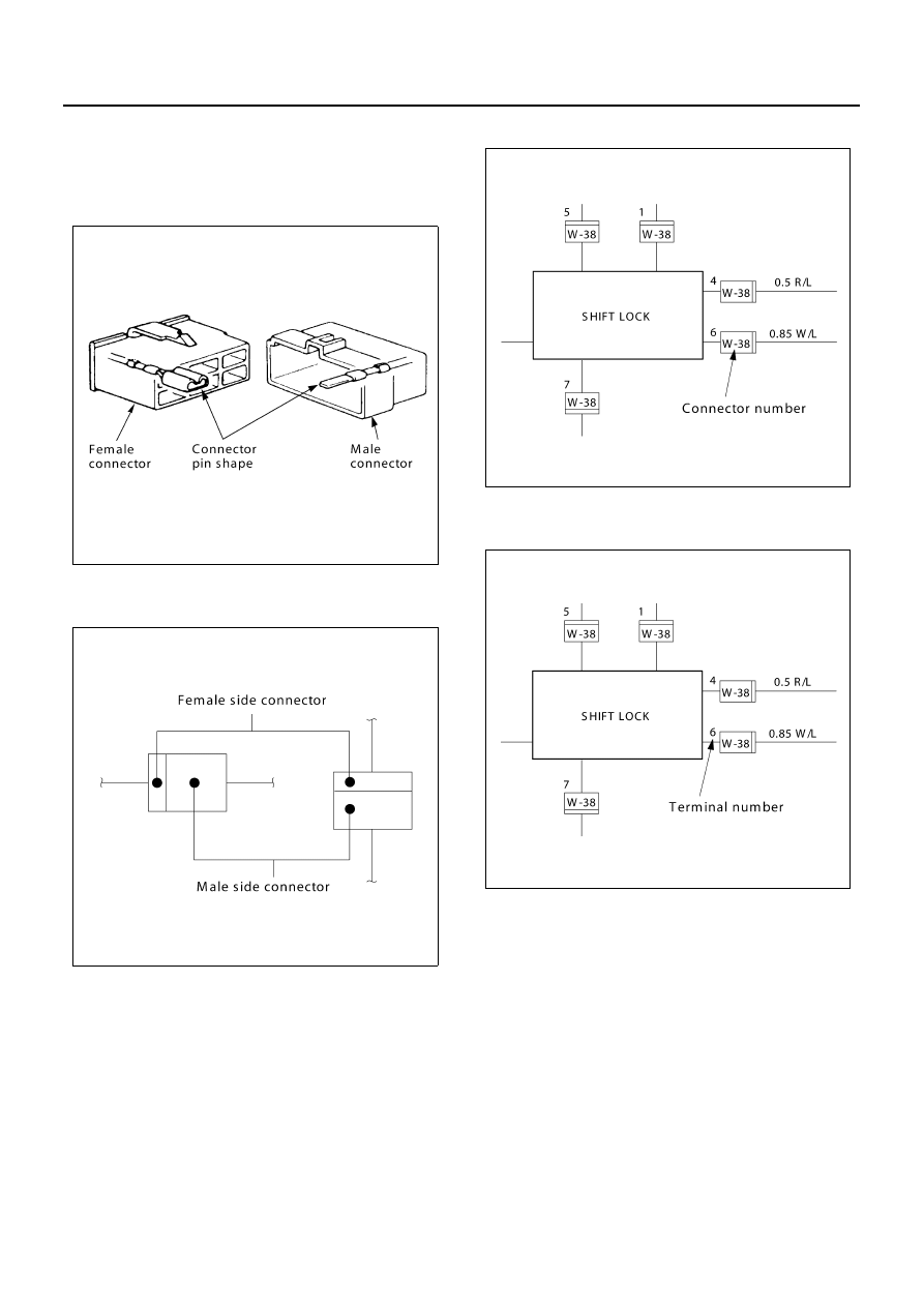
Connector
The connector pin shape determines whether the con-
nector is male or female.
The connector housing configuration does not deter-
mine whether a connector is male or female.

The symbol illustrated in the figure is used as connector,
in the circuit of this section.

Connector is identified with a number.

The applicable terminal number is shown for each con-
nector.

Connector terminal numbers are clearly shown.
Male side connector terminal numbers are in sequence
from upper right to lower left.
Female side connector terminal numbers are in se-
quence from upper left to lower right.

N8A0033E

N8A0034E

N8A0035E

N8A0036E

8-18 CAB AND CHASSIS ELECTRICAL

Notice:
For those connectors on which specific terminal num-
bers or symbols are shown (such as ECM), the terminal
numbers or symbols are used in the circuit diagram, ir-
respective of the above rule.

The connectors used for relays have their own terminal
number assignment, irrespective of the above rule.

N8A0037E

N8A0038E

N8A5038E

CAB AND CHASSIS ELECTRICAL 8-19

Reading The Circuit Diagram

In this manual, each system has its own parts location illustration, circuit diagram and connector configuration used
in the circuit diagram.

Parts Location

The parts location shows the location of the parts 1 and the connector 2 used in each harness routing 3.

N8A0040E

8-20 CAB AND CHASSIS ELECTRICAL

Circuit Diagram

The circuit diagram shows the power supply 4 the load or loads 5 and the grounding point(s) 6.

N8A5040E


Content   ..  976  977  978  979   ..