Isuzu N-Series. Service manual - part 942


  Index      Isuzu     Isuzu N-Series - service and repair manual


Search            


Content   ..  940  941  942  943   ..


Isuzu N-Series. Service manual - part 942


7B-4 Automatic Transmission (Smoother)


The Smoother transmission is based on the MYY type
transmission, with the clutch system changed to the fluid
coupling plus gearshift clutch, and the gearshift control
box changed to a solenoid system. The transmission
receives shift lever and accelerator operation signals
and other data, and automatically engages and
disengages the gearshift clutch (wet-type multi-disc
clutch) and lock up clutch (inside the fluid coupling) to
control gear shifting. 
The following are the basic operation conditions. 

1. Gearshift control box

A new solenoid type control box enables electronic
control of the gear shift/select operation. A
selectable driving mode allows selection of manual
mode shifting or auto shift mode (shift up and
down) can be selected in accordance with the
application using the + / 

− switch.

2. Gearshift clutch

When shifting, the gearshift clutch releases
(disengages) and gear shift control is enabled. 
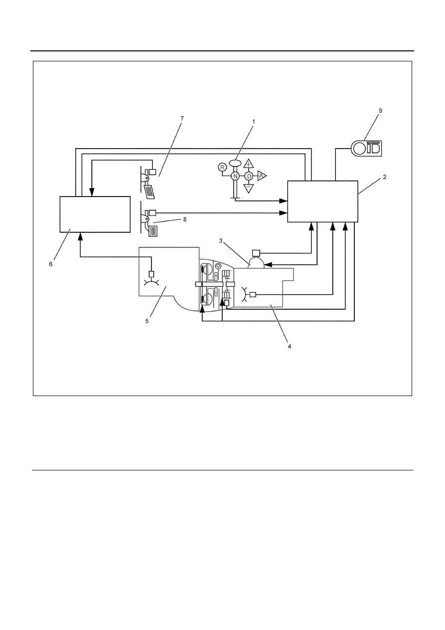
Legend

1. Selector Lever Unit

6. Engine Control Module (ECM)

2. Transmission Control Module (TCM)

7. Accelerator Opening Angle Signal

3. Gearshift Control Box

8. Brake Signal

4. Transmission

9. Instrument Panel Cluster (Lamps, Indicators)

5. Engine

N7A1002E

Automatic Transmission (Smoother) 7B-5

• Gearshift clutch release control

The gearshift clutch is disengaged in neutral
gear. However, at transmission fluid
temperatures of 20

°C or lower, the gearshift

clutch is engaged even in neutral gear (in order
to warm up the transmission). 

• Gearshift clutch control engagement control 

The gearshift clutch engages after shift
completion is detected (gear in determined). 

3. Lock up clutch

While running at or above a preset speed, the lock
up clutch engages in order to eliminate engine
power transmission loss (and increases fuel
consumption). 

• Lock up clutch engagement control 

The lock up clutch disengages when the
following conditions are satisfied: 2nd gear or
higher, transmission speed above a prescribed
value (vehicle speed depends on gear), etc.
The lock up clutch does not engage in the case
of reverse or 1st gear. 

• Lock up clutch control 

The lock up clutch disengages when the
following conditions are satisfied: 2nd gear or
higher, transmission speed below a prescribed
value (vehicle speed depends on gear), etc.

MYY Transmission 

There are two types of MYY transmission: MYY6P and
MYY5T. The MYY transmission is designed for light
weight and increased allowable input torque. New
technology makes it possible to adopt aluminum
cylinder case (3-piece) construction, taper roller
bearings (counter shaft front and rear), a twin rod type
shift control layout, and more. 

7B-6 Automatic Transmission (Smoother)

Part Location Diagram


Legend

1. Oil Pump

7. Bolt

2. Bolt

8. Fluid Coupling

3. Lock Up Clutch

9. Oil Pump Assembly (Oil Control Unit) 

4. Flywheel Housing

10. Clutch Assembly

5. Pilot Hub

11. Brake Band

6. Flex Plate

12. MYY Transmission 

N7A1003E

Automatic Transmission (Smoother) 7B-7

Function Check:

Transmission Fluid Level Check

Smoother

1. Inspection procedure 

a. Stop the vehicle on a level surface, select

neutral gear, and engage the parking brake. 

b. With the engine idling, shift to 2nd gear for at

least three seconds, and then return to neutral.
Repeat this operation at least three times. (For
the second and subsequent shifts, you can
select another gear other than 2nd; also you
can use gear in learning as a substitute for
this.) 
It can be performed to stall the engine while
gearshifts, but stop this immediately when the
alarm bleeps. Even if the alarm does not bleep,
finish this within five seconds. After oil
temperature stabilizes, check the oil level. 

c. With the engine still idling, use the level gauge

to confirm that the oil level is within the
appropriate range for the oil temperature. 
If the oil level is low, replenish it with Besco ATF
III through the level gauge guide tube. 

2. Caution 

• Before pulling out the level gauge, clean the

area around the gauge by wiping with a cloth. 

• Take care to ensure that the cloth is free of lint,

dust, water, or any other foreign matter that can
contaminate the oil. 

• When checking the oil level securely hook the

level gauge to the clip, insert the level gauge
into the guide tube, and hold it there for at least
three seconds before pulling it out for reading. 
Insert the level gauge slowly in order to allow
air to escape. 

• When inserting or pulling out the level gauge,

take care to avoid letting any oil on the filler
tube walls adhere to the level gauge. 

• Use the Tech 2 for an accurate reading of the

oil temperature. For information about using
the Tech 2, refer to “Transmission Control
System Smoother.”

3. Changing transmission fluid procedure

a. Prepare the container under drain plug for

draining of transmission fluid.

b. Pulling out the level gauge.
c. Drain the transmission fluid by remove the

drain plug and O-ring.

d. Tighten the drain plug.

The transmission case is made of aluminium. It
is easily damaged. Be careful not to tighten a
bolt too much.

Tighten:
39 N

⋅m (4.0 kg⋅m / 28.8 lb⋅ft)

Legend

1. Oil level limit when oil temperature is 70 to 80

°

2. Oil level limit when oil temperature is 20 to 30

°

N7A1004E


Content   ..  940  941  942  943   ..