Isuzu N-Series. Service manual - part 883
7C-8 CLUTCH (FOR MZZ TRANSMISSION)
COMPONENT PARTS REPLACEMENT
Clutch Assembly
Remove or Disconnect
1. Transmission assembly.
Refer to TRANSMISSION.
2. Pressure plate assembly.
3. Clutch disc assembly.
4. Return spring.
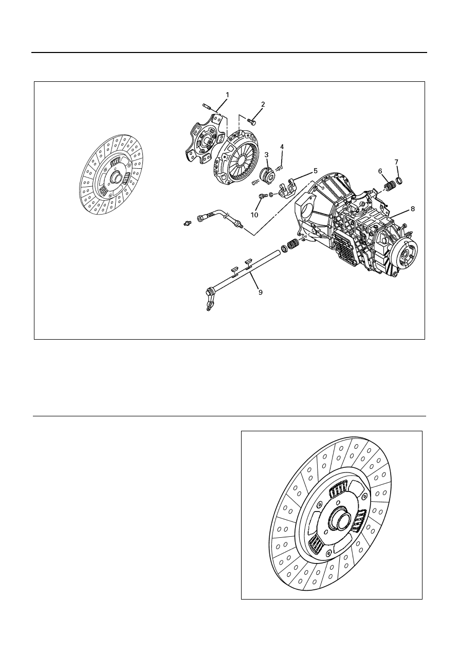
Legend
1. Clutch disc assembly
6. Needle bearing
2. Pressure plate assembly
7. Dust cover
3. Shift block and release bearing
8. Transmission assembly
4. Return spring
9. Clutch shaft
5. Shift fork
10. Set bolt
N7A0545E
N7A0546E