Isuzu N-Series. Service manual - part 802


  Index      Isuzu     Isuzu N-Series - service and repair manual


Search            


Content   ..  800  801  802  803   ..


Isuzu N-Series. Service manual - part 802


 Engine Control System (4JH1)    6E-259
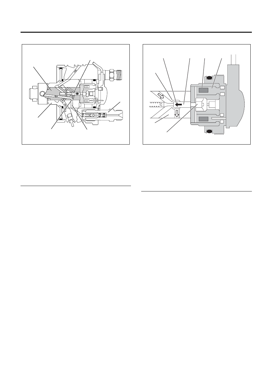
Distributor Head

Legend

1. Rotor Shaft
2. Valve Needle
3. Constant Pressure Valve (CPV) Holder
4. High Pressure Outlet
5. Distributor Shaft
6. Barrel


The distributor head distribute the high pressure fuel
that has flowed through the rotating rotor shaft’s
distributor slits and the barrel’s high pressure outlets (4
cylinders) to the engine cylinders via the constant
pressure valve (CPV) and the nozzle holder
assemblies.  The fuel injection solenoid valve needle
changes the passage to the radial plunger high
pressure pump between fuel suction and fuel
compression.

Fuel Injection Solenoid Valve

Legend

1. Valve Seat
2. Valve Closing Direction
3. Valve Needle
4. Coil
5. Magnet
6. Magnet Anchor
7. Rotor Shaft


The fuel injection solenoid valve consists of a valve
seat, a valve needle, and a magnet anchor (a movable
iron core), a coil and a magnet.  The valve needle
rotates together with the rotor shaft.  When current
controlled by the fuel injection pump control unit (PCU)
flows to the coil, the magnet anchor and the valve
needle are pushed towards the valve seat.  When the
valve seat is completely closed by the valve needle, the
fuel in the high pressure passage is isolated from the
low pressure passage, is compressed by the radial
plunger high pressure pump, and injected into the
engine cylinder through the nozzle holder assembly.
When the required injection quantity is reached, the
current to the coil is cut, the valve seat opens and
injection of fuel is completed.

1

2

3

4

5

6

N6A3848E

1

2

3

4

5

7

6

N6A3849E

6E-260    Engine Control System (4JH1) 

Constant Pressure Valve (CPV)

Legend

1. Plug
2. Ball
3. Seat
4. Valve
5. Spacer
6. Holder
7. Valve Spring
8. Oriffice
9. Ball Support

10. Spring


The constant pressure valve (CPV) consists of a
holder, a spacer, a valve spring, a valve, a seat, a ball,
a ball support, a spring and a plug.  The valve is
equipped with an orifice to suppress the reflected
pressure wave (the cause of secondary injection)
caused by nozzle closing at the end of the injection and
maintains a stable pressure in the injection pipe
(residual pressure) to ensure stabilized injection timing
for subsequent injection.  The valve is opened by
pressurized fuel and this high pressure fuel is delivered
to the nozzle holder assembly.

Timing Control Device Description

Legend

1. Cam Ring
2. Servo Valve
3. Timer Piston
4. Outlet
5. Feed Pump
6. Inlet
7. Fuel Suction
8. Ball Pin
9. Annular Chamber

10. Hydraulic Stopper

11. Return Passage

12. Timing Control Valve (TCV)


The timing device determines the optimum injection
timing against variations in engine speed.  The
pressure of the fuel fed from the feed pump is adjusted
in accordance with speed by the regulating valve.  This
delivery pressure acts on the hydraulic stopper’s
annular chamber as control pressure.  The chamber
pressure of the annular chamber is controlled by the
timing control valve (TCV).  The timing plunger is
connected to the cam ring by a ball pin.  Axial
movement of the timing plunger is transferred to the
cam ring in the form of rotational movement.
Movement to the right of the timing plunger (to the
spring side) advances injection timing.  The main
components are timing plunger, the TCV and pump
camshaft position (CMP) sensor.

1

2

3

4

5

6

10

9

8

7

N6A3850E

1

2

3

4

5

6

7

8

9

10

11

12

N6A3851E

 Engine Control System (4JH1)    6E-261

Beginning of Injection Staring

The engine control module (ECM) contains
characteristic maps of the beginning of injection,
corresponding to engine operating conditions (engine
load, engine speed and engine coolant temperature).
The fuel injection pump control unit (PCU) is constantly
comparing the set beginning of injection timing and the
actual beginning of injection timing.  If there is a
difference, the timing control valve (TCV) is controlled
by the duty ratio.  (The actual beginning of injection
timing is determined from the pump camshaft position
(CMP) sensor.)

Timing Control Valve

Legend

1. Coil
2. From Annular Chamber
3. To Feed Pump
4. Orifice
5. Valve Needle


The timing control valve (TCV) acts as a variable
throttle, using the rapid opening and closing (cycling) of
the valve needle in the TCV.  At normal operation, the
TCV controls the pressure acting on the annular
chamber so that the hydraulic stopper cam move to any
position, from the retard position to the advance
position.  At this time, the duty ratio is set by the fuel
injection pump control unit (PCU).
When control current flows to the TCV coil, the valve
needle opens and the fuel annular chamber flows
through the orifice to the feed pump inlet.
Consequently, the pressure of the annular chamber
decreases and the hydraulic stopper is moved to the
retard side.
When control current to the TCV coil is cut, the valve
needle closes and the return passage is closed.
Consequently, the pressure of the annular chamber
increases and the hydraulic stopper is moved to the
advance side.

Pump Camshaft Position (CMP) Sensor

Legend

1. Pump Camshaft Position (CMP) Sensor
2. Flexible Connecting Harness
3. Drive Shaft
4. Pump Camshaft Position (CMP) Sensor

Retaining Ring

5. Sensor Wheel


When the drive shaft rotates, the pump camshaft
position (CMP) sensor receives signal from the sensor
wheel, and an electric pulse is sent through the flexible
connecting harness to the fuel injection pump control
unit (PCU).  From these signals the PCU can determine
the average pump speed and the momentary pump
speed.  The pump CMP sensor is mounted to the cam
ring.  Thus, the relationship between the cam ring and
the pump CMP sensor signal is constant.  The pump
CMP sensor signal is utilized for the following
purposes:

Engine

Control
Module

(ECM)

Timing

Control

Valve

(TCV)

Fuel

Injection

Pump

Control

Unit

(PCU)

Pump Camshaft
Position (CMP)
Sensor

Engine Load

Engine Speed

Engine Coolant
Temperature

N6A3852E

1

2

3

4

5

N6A3853E

1

5

4

2

3

N6A3854E

6E-262    Engine Control System (4JH1) 

• To determine the momentary angular position of

the cam ring.

• To calculate the actual speed of the fuel injection

pump.

• To determine the actual timing plunger position.

Legend

1. Pump Camshaft Position (CMP) Sensor Signal
2. Crankshaft Position (CKP) Sensor Signal
3. Fuel Injection Solenoid Valve Control Pulse
4. Fuel Injection Solenoid Needle Valve Lift
5. Cam Lift (Cam Profile)
6. Pulse Count
7. Fuel Injection Solenoid Valve Close
8. Fuel Injection Solenoid Valve Open
9. Start of Pressure Delivery

10. End of Pressure Delivery

11. Pressure Delivery Angle

12. Effective Stroke


• Momentary Cam Ring Angular Position

The momentary angular position of the cam ring is
input into the fuel injection PCU as a fuel injection
solenoid valve control signal.  From momentary
input of angular position for fluctuations in running
conditions, the fuel injection solenoid valve open
and close intervals corresponding to the cam ring’s
cam lift can be accurately determined.

• Actual Injection Pump Speed

When the crankshaft speed (CKP) sensor is faulty,
the engine control module (ECM) uses the pump
CMP signal as a replacement signal.

• Actual Timing Plunger Position

The actual timing plunger position can be
determined by comparing the CKP sensor signal
with the pump CMP sensor angle.  This position is
used for timer control.

1

6

7

9

8

10

11

12

2

3

4

5

N6A3855E


Content   ..  800  801  802  803   ..