Isuzu N-Series. Service manual - part 730


  Index      Isuzu     Isuzu N-Series - service and repair manual


Search            


Content   ..  728  729  730  731   ..


Isuzu N-Series. Service manual - part 730


6E-342    Engine Control System (4HK1) 

14. Install the fuel injector terminal nuts to the injector.

Tighten:
Nut to 2 N

⋅m (0.2 kg⋅m / 17 lb⋅in)

Caution:

• Do not overtighten the nuts. Damage to the terminal

studs will result.

• The terminal nut with two wires is engine front side.

Legend

1. Fuel Injector
2. Harness
3. Terminal Nut


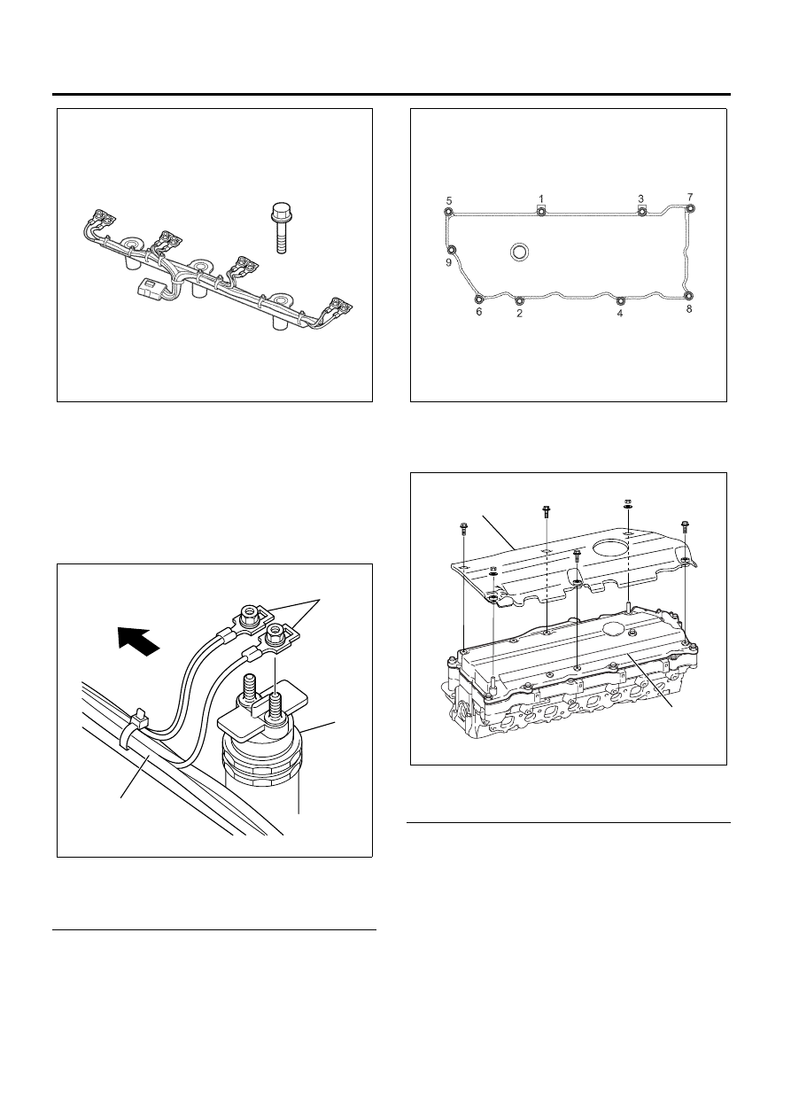
15. Install the gasket to the cylinder head cover.
16. Install the cylinder head cover and tighten up

according to the order.

Tighten:
Bolts to 18 N

⋅m (1.8 kg⋅m / 13 lb⋅ft)

17. Install the sound insulation cover (For Europe)

Tighten:
Bolts to 8 N

⋅m (0.8 kg⋅m / 6 lb⋅ft)

Legend

1. Sound Insulation Cover (For Europe)
2. Head Cover


18. Install the gasket to the EGR valve and tighten the

bolts to the specified torque.

Tighten:
Bolts to 24 N

⋅m (2.4 kg⋅m / 17 lb⋅ft)

19. Install the gasket to the EGR adapter and tighten

the bolts to the specified torque.

Tighten:
Bolts to 24 N

⋅m (2.4 kg⋅m / 17 lb⋅ft)

N6A6182E

N6A6627E

2

1

3

N6A6029E

1

2

N6A6027E

 Engine Control System (4HK1)    6E-343

Legend

1. EGR Adapter
2. EGR Valve Gasket
3. EGR Valve
4. EGR Valve Gasket


20. Attach the engine harness connectors. Each

composite connector should make a loud click
when it is securely attached.

Fuel Injector ID Code Data Programming Procedure

1. Install the Tech 2.
2. Turn ON the ignition, with the engine OFF.
3. Select Diagnostics > appropriate vehicle

identification > 4HK1 (Common Rail) >
Programming > Injector ID Code > ID Code
Registration.

4. Select replaced cylinder and press Change. Input

22 figures. Then, input in order from the left edge
of upper sequence to the right sequence. The
correct order for the fuel injector ID code for the
following illustration is as follows:
56 00 D1 CA 00 00 EC 00 23 14 21

Important:
The number of places required for input is 22 figures
except last 2 figures.

Legend

1. Fuel Injector ID Plate
2. Fuel Injector ID Code
3. Fuel Injector


5. After complete the registration, turn OFF the

ignition for 30 second.

6. Turn ON the ignition.
7. Select Diagnostics > appropriate vehicle

identification > 4HK1 (Common Rail) >
Programming > Injector ID Code > Injector ID
Code. At this point, all registered fuel injector ID
code data can be verified. Compare the ID code
values registered into the ECM and each fuel
injector including the last 2 figures. If the registered
ID code is incorrect, go back to Step 4 ID Code
Registration.

8. Start the engine and let idle.
9. Inspect for a proper engine running condition and

for no DTC’s. Refer to the Diagnostic System
Check-Engine Controls if needed.

Notice:
After replacement of the fuel injector, perform the
following procedure.
All fuel injectors are replaced:
Remove the fuel injector ID code label on the cylinder
head cover.
Any fuel injector(s) is replaced:
Blackout the replaced cylinder fuel injector ID code on
the cylinder head cover with a marking pen or
equivalent.

N6A6371E

D1CA
EC00
2100
B7

5600
0000
2314
0000

1

2

3

N6A6525E

6E-344    Engine Control System (4HK1) 

Fuel Rail Pressure (FRP) Sensor
Replacement

Removal Procedure
WARNING:
TO PREVENT LEAKED FUEL FROM CATCHING
FIRE, DO NOT WORK WHILE THE ENGINE IS HOT.

Preparation:

• Pour detergent into a steam cleaner, and throughly

wash around the sensor and the fuel rail.

• Remove water completely using air blow.

Notice:
Make sure that foreign matter will be prevented from
getting in.

1. Remove the air intake pipe.
2. Disconnect the fuel rail pressure (FRP) sensor

connector.

3. Remove the FRP sensor.

Legend

1. Fuel Rail Pressure (FRP) Sensor


Installation Procedure
Important:

• FRP sensor cannot be reused after assembly. (The

seal is deformed after tightening. This may result in
defective seal if reused.)

• Keep the protective cap attached until assembly.
• Take care not to allow water or foreign matter to

get inside the connector.

• Do not let foreign matter attach to the threaded

portion. Also, make sure the installation part is free
of foreign matter before installation.

1. Apply grease to the threads of the FRP sensor.

2. Install the FRP sensor.

Tighten:
FRP sensor to 98 N

⋅m (10 kg⋅m / 72 lb⋅ft)

Legend

1. Fuel Rail Pressure (FRP) Sensor


3. Connect the FRP sensor connector.
4. Install the air intake pipe.

Notice:

• Carefully check for fuel leak after starting the

engine.

• After the sensor is replaced, clear the trouble code

and make sure the sensor operates normally using
a scan tool.

Fuel Pressure Limiter Replacement

Removal Procedure
WARNING:
TO PREVENT LEAKED FUEL FROM CATCHING
FIRE, DO NOT WORK WHILE THE ENGINE IS HOT.

Preparation:

• Pour detergent into a steam cleaner, and throughly

wash around the sensor and the fuel rail.

• Remove water completely using air blow.

Notice:
Make sure that foreign matter will be prevented from
getting in.

1. Remove the air intake pipe.
2. Remove the fuel leak off hose from the leak off

pipe.

• Cover the removed fuel hose, keep it facing

upward and secure it using wire, etc.

3. Remove the fuel pipe.

1

N6A6580E

1

N6A6580E

 Engine Control System (4HK1)    6E-345

Important:
Loosen the fuel pipe gradually not to scatter high
pressure fuel.

4. Remove the clips and the fuel leak off pipe.

Legend

1. Fuel Pipe
2. Fuel Leak Off Pipe


5. Remove the fuel pressure limiter.

Important:
Do not damage the seat surface when removing the
gasket.

Legend

1. Fuel Pressure Limiter
2. Gasket


Installation Procedure
Important:

• Do not reuse the removed fuel pressure limiter and

gaskets.

• Do not let foreign matter attach to the threaded

portion. Also, make sure the installation part is free
of foreign matter before installation.

1. Install the fuel pressure limiter.

Tighten:
Fuel pressure limiter to 172 N

⋅m (17.5 kg⋅m / 127

lb

⋅ft)

Legend

1. Fuel Pressure Limiter
2. Gasket


2. Tighten the fuel leak off pipe (1) using the

mounting eyebolt and the clips using the specified
torque.

Tighten:
(2): 18 N

⋅m (1.8 kg⋅m / 13 lb⋅ft)

(3): 12 N

⋅m (1.2 kg⋅m / 9 lb⋅ft)

(4): 8 N

⋅m (0.8 kg⋅m / 69 lb⋅in)

3. Tighten the fuel pipe (5) using the mounting sleeve

nut and the clip using the specified torque.

Tighten:
(6): 44 N

⋅m (4.5 kg⋅m / 33 lb⋅ft)

(7): 6 N

⋅m (0.6 kg⋅m / 52 lb⋅in)

(8): 44 N

⋅m (4.5 kg⋅m / 33 lb⋅ft)

2

1

N6A6581E

2

1

N6A6582E

2

1

N6A6582E


Content   ..  728  729  730  731   ..