Isuzu N-Series. Service manual - part 654


  Index      Isuzu     Isuzu N-Series - service and repair manual


Search            


Content   ..  652  653  654  655   ..


Isuzu N-Series. Service manual - part 654


6E-38    Engine Control System (4HK1) 

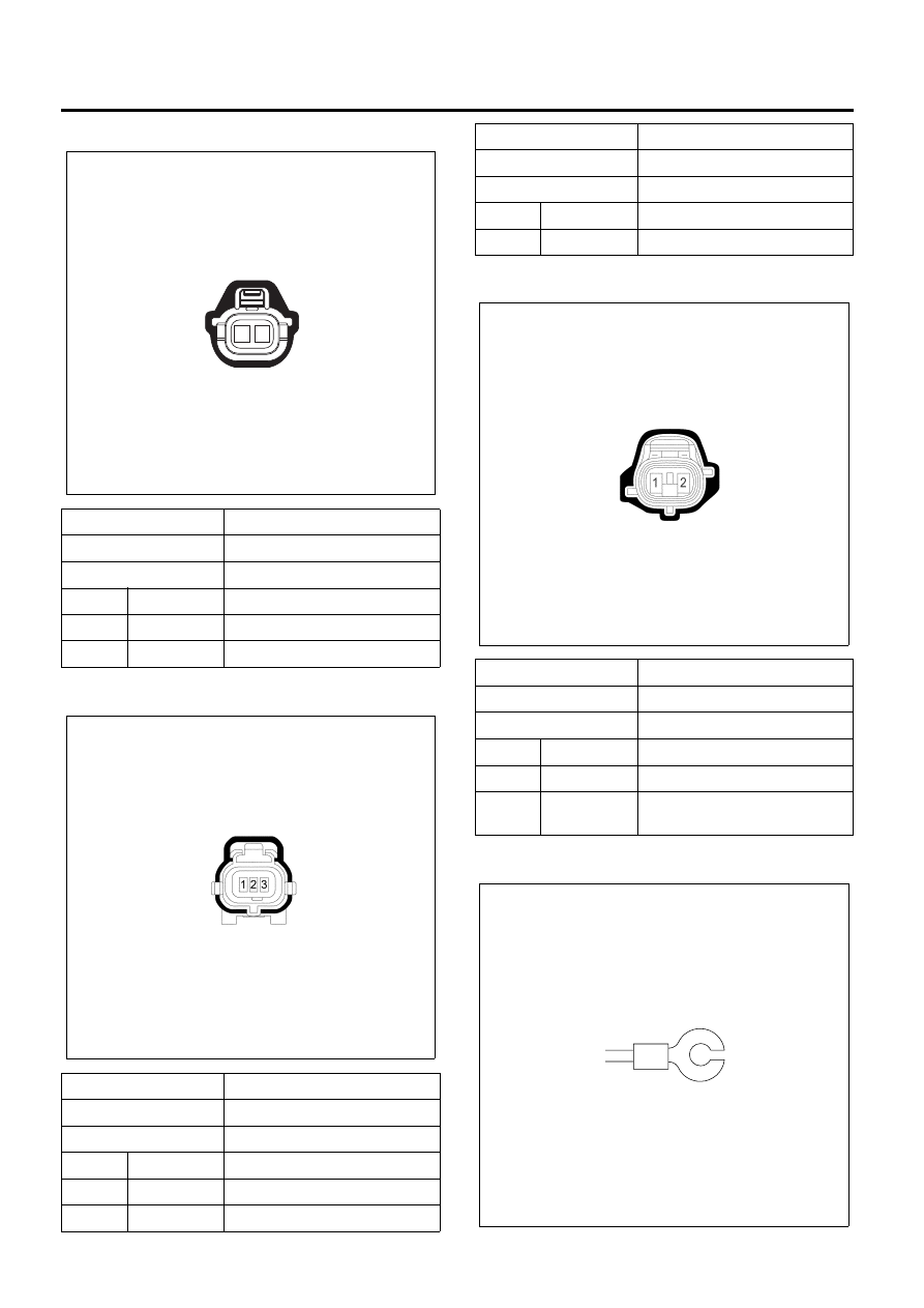
Fuel Rail Pressure (FRP) Regulator

Fuel Rail Pressure (FRP) Sensor

Fuel Temperature (FT) Sensor

Glow Plug

Connector No.

E-116

Connector Color

Gray

Test Adapter No.

J-35616-33

Pin

Wire Color

Pin Function

1

WHT/RED

FRP Regulator High Control

2

GRN/RED

FRP Regulator Low Control

Connector No.

E-113

Connector Color

Black

Test Adapter No.

J-35616-64A

Pin

Wire Color

Pin Function

1

BRN

FRP Sensor Low Reference

2

WHT

FRP Sensor Signal

1

2

N6A6455E

N6A6555E

3

GRN/BLU

FRP Sensor 5 Volts Reference

Connector No.

E-93

Connector Color

Green

Test Adapter No.

J-35616-64A

Pin

Wire Color

Pin Function

1

BLK

FT Sensor Low Reference

2

LT GRN/

WHT

FT Sensor Signal

Connector No.

E-113

Connector Color

Black

Test Adapter No.

J-35616-64A

Pin

Wire Color

Pin Function

N6A6556E

N6A3809E

 Engine Control System (4HK1)    6E-39

Idle Up Sensor

Intake Air Temperature (IAT) Sensor

Intake Throttle Solenoid Valve

Connector No.

E-3

Connector Color

Silver

Pin

Wire Color

Pin Function

1

BLK/YEL

Power Supply

Connector No.

B-281

Connector Color

White

Test Adapter No.

J-35616-33

Pin

Wire Color

Pin Function

1

BLU/RED

Idle Up Sensor Low Reference

2

BLU/YEL

Idle Up Sensor Signal

3

BLU

Idle Up Sensor 5 Volts 
Reference

1

2

3

N6A6467E

1 2

N6A6468E

Connector No.

J-190

Connector Color

Gray

Test Adapter No.

J-35616-16

Pin

Wire Color

Pin Function

1

RED/GRN

IAT Sensor Signal

2

BLK

IAT Sensor Low Reference

Connector No.

J-40

Connector Color

Black

Test Adapter No.

J-35616-4A

Pin

Wire Color

Pin Function

1

LT  GRN

Intake Throttle Solenoid Valve 
Voltage Feed

2

LT GRN/

WHT

Intake Throttle Solenoid Valve 
Control

1 2

N6A6469E

6E-40    Engine Control System (4HK1) 

PTO Switch

PTO Throttle Sensor

Vehicle Speed Sensor (VSS)

Connector No.

B-84

Connector Color

White

Test Adapter No.

J-35616-33

Pin

Wire Color

Pin Function

1

BLU/ORG

PTO Switch Signal

2

BLK

PTO Switch Ground

Connector No.

J-166

Connector Color

White

Test Adapter No.

J-35616-33

Pin

Wire Color

Pin Function

1

RED

PTO Throttle Sensor 5 Volts 
Reference

2

BRN

PTO Throttle Sensor Signal

1 2

N6A6470E

1

2

3

N6A6643E

3

PNK/BLK

PTO Throttle Sensor Low 
Reference

Connector No.

J-32

Connector Color

Gray

Test Adapter No.

J-35616-33

Pin

Wire Color

Pin Function

1

BLK/YEL

VSS Ignition Voltage

2

BLK

VSS Low Reference

3

YEL/GRN

VSS Signal

Connector No.

J-166

Connector Color

White

Test Adapter No.

J-35616-33

Pin

Wire Color

Pin Function

1

2

3

N6A3813E

 Engine Control System (4HK1)    6E-41

Diagnostic Information and Procedures

General Service Information

Non-OEM Parts
All of the on-board diagnostic (OBD) has been
calibrated to run with original equipment manufacturer
(OEM) parts. Accordingly, if commercially sold sensor
or switch is installed, it makes a wrong diagnosis and
turn on the malfunction indicator lamp (MIL).
Aftermarket electronics, such as cellular phones,
stereos, and anti-theft devices, may indicate
electromagnetic interference (EMI) into the control
system if they are improperly installed. This may cause
a false sensor reading and turn on the MIL.

Poor Vehicle Maintenance
The sensitivity of OBD will cause the MIL turn on if the
vehicle is not maintained properly. Restricted oil filters,
fuel filters, and crankcase deposits due to lack of oil
changes or improper oil viscosity can trigger actual
vehicle faults that were not previously monitored prior
to OBD. Poor vehicle maintenance cannot be classified
as a “non-vehicle fault”, but with the sensitivity of OBD
diagnostics, vehicle maintenance schedules must be
more closely followed.

Visual / Physical Engine Compartment Inspection
Perform a careful visual and physical engine
compartment inspection when performing any
diagnostic procedure or diagnosing the cause of an
emission test failure. This can often lead to repairing a
problem without further steps. Use the following
guidelines when performing a visual / physical
inspection:

• Inspect all vacuum hoses for punches, cuts,

disconnects, and correct routing.

• Inspect hoses that are difficult to see behind other

components.

• Inspect all wires in the engine compartment for

proper connections, burned or chafed spots,
pinched wires, contact with sharp edges or contact
with hot exhaust manifolds or pipes.

Basic Knowledge of Tools Required
Lack of basic knowledge of this powertrain when
performing diagnostic procedures could result in an
incorrect diagnosis or damage to powertrain
components. Do not attempt to diagnose a powertrain
problem without this basic knowledge. A basic
understanding of hand tools is necessary to effectively
use this section of the manual.

Malfunction Indicator Lamp (MIL)
Basically, the MIL is turned on when the ECM detects a
DTC that will impact the vehicle emission or
performance. When the MIL remains “ON” while the
engine is running, or when a malfunction is suspected
due to a driveability or emissions problem, a Diagnostic
System Check must be performed. The procedures for
these checks are given in Diagnostic System Check -
Engine Controls.

DTC Types
Characteristic of Code

• Stores a DTC on the first trip with a fail
• Dose not request illumination of any lamp

Reading Flash Diagnostic Trouble Codes (DTC)
The provision for communicating with the ECM is the
Data Link Connector (DLC). The DTCs stored in the
ECM memory can be read either through a hand-held
diagnostic scanner such as Tech 2 plugged into the
DLC or by counting the number of flashes of the MIL
when the diagnostic test terminal of the DLC is
grounded. The DLC terminal “1” (diagnostic request) is
pulled “Low” (grounded) by jumped to DLC terminal “4”,
which is a ground wire. Once terminals “1” and “4” have
been connected, the ignition switch must be moved to
the “ON” position, with the engine not running. The MIL
will indicate a DTC three times is a DTC is present and
history. If more than one DTC has been stored in the
ECM’s memory, the DTCs will be output numerical
order with each DTC being displayed three times. The
flash DTC display will continue as long as the DLC is
shorted.


Content   ..  652  653  654  655   ..