Isuzu N-Series. Service manual - part 639


  Index      Isuzu     Isuzu N-Series - service and repair manual


Search            


Content   ..  637  638  639  640   ..


Isuzu N-Series. Service manual - part 639


6E-4 EXHAUST GAS RECIRCULATION (EGR) SYSTEM

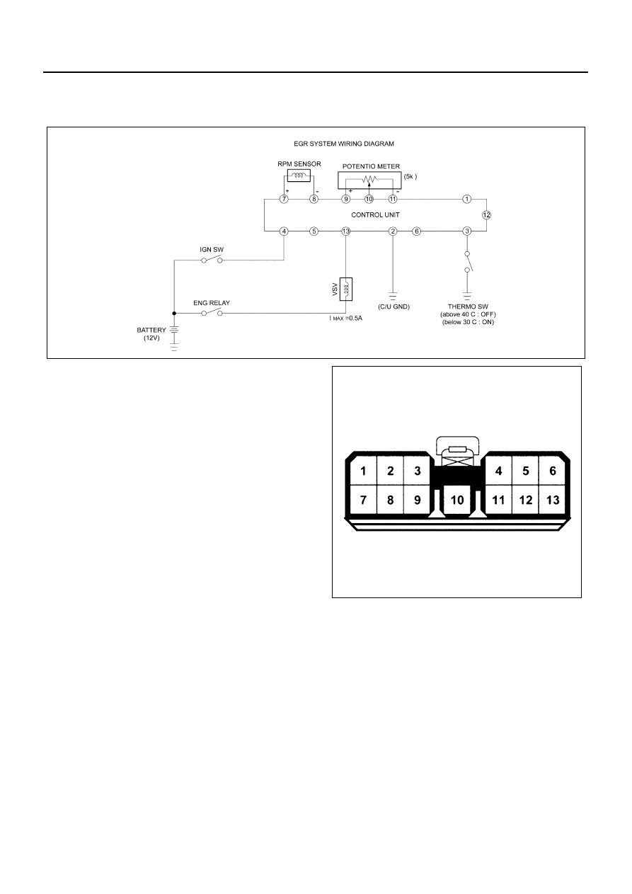
EGR SYSTEM WIRING DIAGRAM

For 4JB1-TC/4JG2

1. Connector Pin Assignment

N6A3580E

No.

Connector Name

1

2

Battery (

−) c/u GND

3

Thermo Switch

4

Battery (+)

5

6

7

rpm Signal (+)

8

rpm Signal (

−)

9

Potentiometer (+)

10

Potentiometer

11

Potentiometer (

−)

12

13

VSV

N6A3581E

EXHAUST GAS RECIRCULATION (EGR) SYSTEM 6E-5

EGR SYSTEM OPERATION

1. On the input side of engine speed, there is provided a hysteresis of 50 rpm on the speed rising side.
2. It does not work until 70 seconds, pass after engine start.
3. It does not work while the water temperature switch is on (30

°C or lower).

4. While engine speed drops from 3,800 rpm or higher, it does not work for 25 seconds.

Exhaust Gas Recirculation (EGR) System Check

Step

Action

Value

YES

NO

1

Check the EGR valve for looseness.

Is the EGR valve loose?

Go to Step 2

Go to Step 3

2

Tighten the EGR valve.

Is the action complete?

Verify repair

3

1. Engine “OFF”.
2. Ignition “ON”.
3. Using test light to ground, check the EGR

harness between the EGR valve and igni-
tion feed.

Does the test light illuminate?

Go to Step 5

Go to Step 4

4

Repair the EGR harness ignition feed.

Was the problem corrected?

Verify repair

Go to Step 5

5

1. Remove the EGR valve.
2. Visually and physically inspect the EGR

valve pintle, valve passages and adapter
for excessive deposits, obstructions or
any restrictions.

Does the EGR valve have excessive deposits,
obstructions or any restrictions?

Go to Step 6

Go to Step 7

6

Clean or replace EGR system components as
necessary.

Was the problem corrected?

Verify repair

Go to Step 7

7

1. Remove the EGR inlet and outlet pipes

from the intake and exhaust manifolds.

2. Visually and physically inspect manifold

EGR ports and EGR inlet and outlet pipes
for blockage or restriction caused by ex-
cessive deposits or other damage.

Do the manifold EGR ports or inlet and outlet
pipes have excessive deposits, obstructions,
or any restrictions?

Go to Step 8

EGR system work-

ing properly. No 

problem found.

8

Clean or replace EGR system components as
necessary.

Is the action complete?

Verify repair

6E-6 EXHAUST GAS RECIRCULATION (EGR) SYSTEM

INSPECTION

Vacuum Switch Valve (VSV)
Check the resistance between the VSV connector termi-
nals using a circuit tester.
Cold Resistance: 37 — 44 (

Ω) (for 12 volt)

Connect battery voltage between VSV connector termi-
nals and make sure of the continuity between the ports.

EGR Valve
With negative pressure applied to the diaphragm cham-
ber, make sure that the valve is smoothly actuated to
make the area between (1) and (2) ventilated.
Startup: About — 18.66

±2.67 Kpa (−140±20 mmHg)

Check to see if EGR valve is normally actuated under
the following conditions:
QWS off (After warming up)
Engine coolant temp: 80

°C or higher

Legend

1. 2 pin
2. Port

N6A3583E

N6A3584E

Illustration

Tool Number / 

Description / Remarks

5-8840-0366-0 / High 

Impedance Multimeter 

(Digital Voltmeter-DVM)

5-8840-0279-0 / Vac-

uum Pump with Gauge

5884003660

5884002790

EXHAUST GAS RECIRCULATION (EGR) SYSTEM 6E-7

EGR COOLER

Component

Removal

Preparation

• Disconnect the battery ground cable.
• Drain the coolant.
• Remove the water hose.

1. EGR Cooler Bracket

Remove the bracket from the flywheel housing.

2. EGR Cooler

Remove the EGR fixing nuts. Remove the cooler
together with the gasket.

3. EGR Pipe
4. EGR Valve

Legend

1. EGR cooler bracket

3. EGR pipe

2. EGR cooler

4. EGR valve

N6A3585E

N6A3586E

Legend

1. EGR cooler
2. EGR cooler bracket

Legend

1. EGR valve
2. EGR pipe

N6A3587E


Content   ..  637  638  639  640   ..