Isuzu N-Series. Service manual - part 525
6C-8 Fuel System
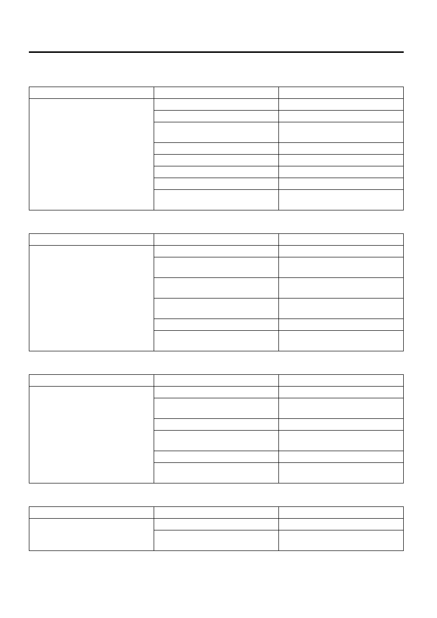
Trouble Shooting
Problems with starting
Unstable idling
Insufficient power
Maximum engine speed is too low
Condition
Possible Cause
Correction
Problems with starting
Fuel tank is empty
Fill the tank.
Air has entered the fuel system.
Bleed the air.
Fuel line is clogged or damaged.
Connection to the fuel line is loose.
Repair or replace the fuel line.
Re-tighten the connection.
Fuel filter element is clogged.
Replace the cartridge.
Fault in the feed pump
Replace the fuel supply pump.
Regulating valve is open.
Replace.
Sticking of the fuel injector nozzle
Replace the fuel injector.
Defective engine control system
Diagnose
the
engine
control
system.
Condition
Possible Cause
Correction
Hunting during idling
Air has entered the fuel system.
Bleed air from the fuel system.
Leakage or clogging of the fuel
system
Repair or replace the fuel system.
Water particles or foreign matter in
the fuel system.
Replace the fuel.
Fuel
filter
element
is
clogged.
Replace the fuel filter element
(cartridge).
Sticking of the fuel injector nozzle
Replace the fuel injector.
Defective engine control system
Diagnose
the
engine
control
system.
Condition
Possible Cause
Correction
Insufficient horsepower
Air has entered the fuel system.
Bleed air from the fuel system.
Leakage or clogging of the fuel
system
Repair or replace the fuel system.
Water mixes in the fuel system
Replace the fuel.
Fuel filter element is clogged.
Replace the element or the
cartridge.
Sticking of the fuel injector nozzle
Replace the fuel injector.
Defective engine control system
Diagnose
the
engine
control
system.
Condition
Possible Cause
Correction
Maximum engine speed is too low
Fuel line is clogged or damaged.
Repair or replace the fuel line.
Defective engine control system
Diagnose
the
engine
control
system.