Isuzu N-Series. Service manual - part 503


  Index      Isuzu     Isuzu N-Series - service and repair manual


Search            


Content   ..  501  502  503  504   ..


Isuzu N-Series. Service manual - part 503


Engine Mechanical (4HK1-TC)   6A-117

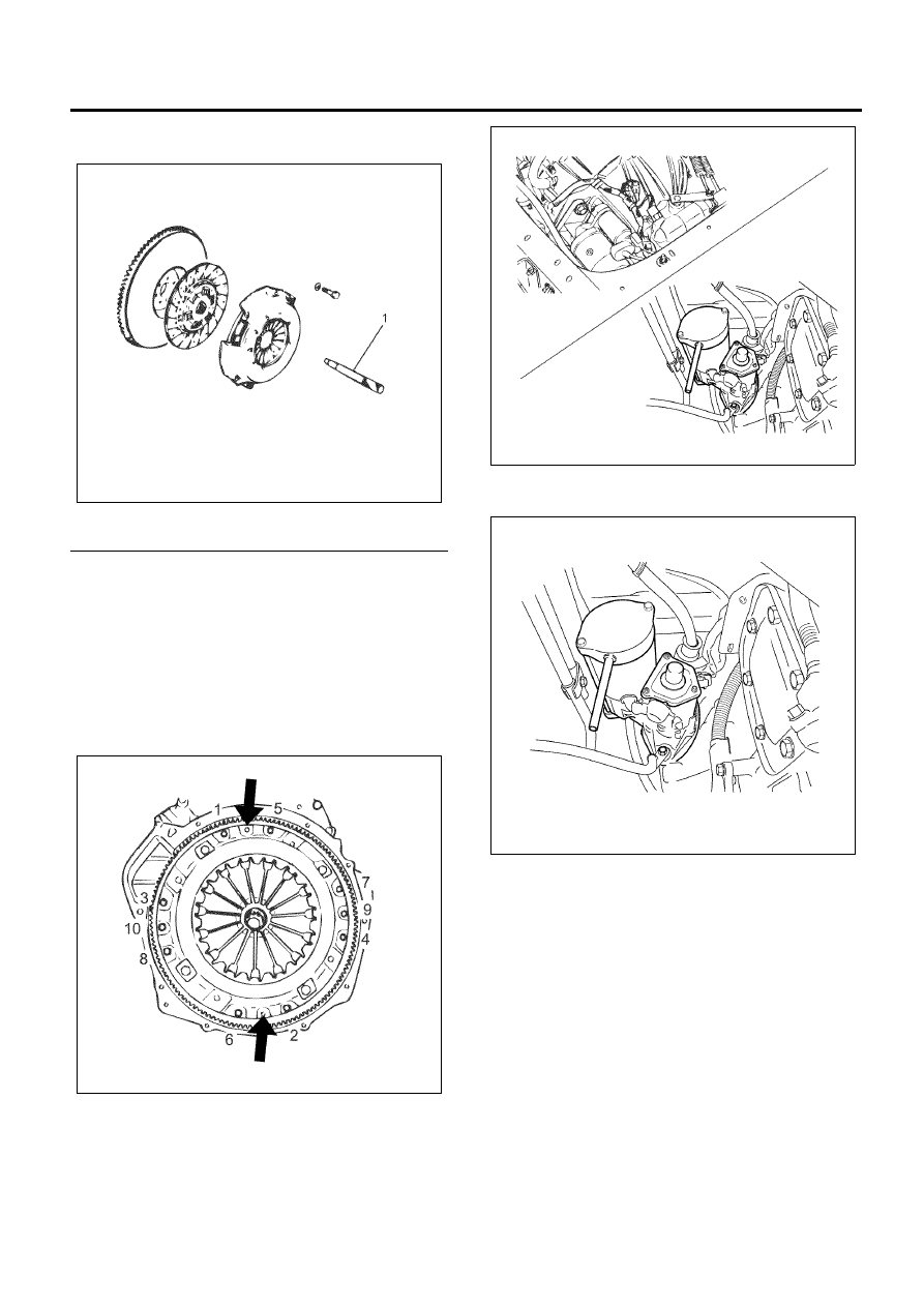
• Use a clutch aligner to install the clutch plate

assembly on the flywheel.

Legend

1. Clutch Aligner


7. Install the clutch pressure plate assembly.

• Install the clutch pressure plate assembly on

the flywheel so that the installation hole of the
clutch pressure plate assembly matches with
the dowel pins of the flywheel.

• Tighten the clutch pressure plate assembly in

the order shown in the drawing.

Tighten:
Bolts to 40 N

⋅m (4.1 kg⋅m/30 lb⋅ft)

8. Install the transmission assembly.

Refer to “Engine Assembly”.

9. Install the starter motor on the clutch housing with

bolts.

Tighten:
Bolts to 76 N

⋅m (7.7 kg⋅m/56 lb⋅ft)

• Install the earth cable of the starter motor.
• Connect the front frame harness connector.

N6A6218E

N6A6217E

N6A6216E

N6A6215E

6A-118   Engine Mechanical (4HK1-TC)

Torque Specifications

Special Tool

N6A6223E

Illustration

Tool Number / 

Description / Remarks

5-8840-2230-0 

(EN-47680)

Crankshaft Stopper

5-8840-0266-0 (J-45059)

Angle Gauge

Engine Mechanical (4HK1-TC)   6A-119

Front Cover

Component

Legend

1. Adjust Plate
2. Generator
3. Front Cover
4. Oil Pan Gasket
5. Oil Pan
6. Rubber Assembly (For Europe)
7. Front Slinger

8. Front Oil Seal
9. Crankshaft Pulley

10. Water Pump Assembly

11. Fan Belt

12. Water Pump Pulley
13. Fan Assembly


Removal

1. Remove the front oil seal.

Refer to “Crankshaft Front Oil Seal”.

2. Remove the oil pan

Refer to “Oil Pan”.

3. Remove the water pump.

Refer to “Water Pump” in Section 6B.

4. Remove the front cover.

N6A6224E

6A-120   Engine Mechanical (4HK1-TC)

• Remove the generator adjust plate.

• Remove the oil relief valve (arrowed), loosen

the front cover installation bolts and remove the
front cover.

5. Remove the oil cooler bypass valve.

• Pull out the oil cooler bypass valve from the

cylinder block.

Installation

1. Install the oil cooler bypass valve.

• Insert the oil cooler bypass valve into the

cylinder block. Be sure not to insert in a wrong
direction.

2. Install the front cover.

• Clean the cylinder block front surface. In

particular, remove liquid gasket leaked during
installation of the crankcase.

• Install two O-rings and apply liquid gasket

(ThreeBond 1207B, 1207C, 1207F or
equivalent) along with the groove of the front
cover installation surface.

N6A6225E

N6A6226E

Beat width:

1.5 – 5mm (0.059 – 0.20 in)

Beat height:

0.3 – 1.5mm (0.012 – 0.059 in) from
the joint surface

N6A6227E

N6A6228E


Content   ..  501  502  503  504   ..