Isuzu N-Series. Service manual - part 483


  Index      Isuzu     Isuzu N-Series - service and repair manual


Search            


Content   ..  481  482  483  484   ..


Isuzu N-Series. Service manual - part 483


Engine Mechanical (4HK1-TC)   6A-37

Legend

1. Oil Outlet 
2. Oil Inlet 


Waste gate operation (absolute pressure)

1. Remove the hose from the waste gate actuator.
2. Install the pressure gauge (general tool). Refer to

the illustration.

Legend

1. Waste Gate Actuator
2. Waste Gate Hose
3. Pressure Gauge (General Tool)


3. Use the pressure gauge pump to apply pressure

(load) to the waste gate actuator (the engine must
be off).

4. Check the pressure and control rod movement.

5. Inspect the hose for cracks and other damage.

Replace the hose if necessary.

6. Do not apply a pressure of more than 200 kPa (1.2

kg/cm

2

 / 29 psi) to the waste gate actuator.
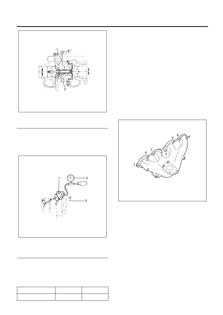
Installation

1. Put the gasket in to install the exhaust manifold.

• Tighten up with the 2 nuts and 6 bolts according

to the order given on the figure.

Tighten:
Bolts (1), (2), (3), (4), (5), (6) and Nuts (7), (8) to 34 N

⋅m

(3.5 kg

⋅m/25 lb⋅ft)

Caution:
Do not tighten up too much because it hampers
expansion and contraction due to the heat from the
manifold.

2. Install the gasket and turbocharger to the exhaust

manifold. Tighten the nuts to the specified torque.

Tighten:
Nuts to 52 N

⋅m (5.3 kg⋅m/38 lb⋅ft)

3. Tighten the adapter bolts (exhaust manifold side)

to the specified torque.

Tighten:
Bolts to 25 N

⋅m (2.5 kg⋅m/19 lb⋅ft)

Movement, mm (in)

0.38 (0.0150)

4.00 (0.1575)

Pressure, kPa (psi)

160 (23)

180 (26)

N6A6044E

N6A6045E

N6A6046E

6A-38   Engine Mechanical (4HK1-TC)

Legend

1. Fixing Nut
2. Exhaust Adapter
3. Fixing Bolt
4. Fixing Nut


4. Install the water feed pipe to the turbocharger. 

• Tighten the joint bolts to the specified torque.

Tighten:
Joint bolts to 41 N

⋅m (4.2 kg⋅m/30 lb⋅ft)

• Install the pipe bracket and tighten the bolts to

the specified torque.

Tighten:
Bolts to 24 N

⋅m (2.4 kg⋅m/17 lb⋅ft)

5. Install the water return pipe. Tighten the joint bolts

to the specified torque.

Tighten:
Joint bolts to 41 N

⋅m (4.2 kg⋅m/30 lb⋅ft)

6. Install the water return pipe bracket. Tighten the

bolts to the specified torque.

Tighten:
Bolts to 24 N

⋅m (2.4 kg⋅m/17 lb⋅ft)

• Install the rubber hose between the water

return pipe and the thermostat housing.

Legend

1. Water Return Pipe
2. Rubber Hose


7. Install the turbocharger oil feed pipe to the top of

the turbocharger. Tighten the joint bolts to the
specified torque.

Tighten:
Joint bolts to 27 N

⋅m (2.8 kg⋅m/19.9 lb⋅ft)

• Install the pipe bracket and tighten the bolts to

the specified torque.

Tighten:
Bolts to 24 N

⋅m (2.4 kg⋅m/17 lb⋅ft)

N6A6040E

N6A6047E

N6A6039E

Engine Mechanical (4HK1-TC)   6A-39

Legend

1. Oil Feed Pipe
2. Water Return Pipe
3. Heat Protector
4. Charge Air Hose
5. Inlet Duct
6. EGR Pipe


8. Tighten the oil return pipe bolts to the specified

torque.

Tighten:
Bolts to
Turbocharger side: 9 N

⋅m (0.9 kg⋅m/78 lb⋅in)

Cylinder block side: 22 N

⋅m (2.2 kg⋅m/15 lb⋅ft)

9. Install the heat protector and tighten the bolts to

the specified torque.

Tighten:
Bolts to 10 N

⋅m (1.0 kg⋅m/87 lb⋅in)

10. Install the air intake duct and tighten the bolts to

the specified torque.

Tighten:
Bolts to 10 N

⋅m (1.0 kg⋅m/87 lb⋅in)

11. Install the charge air pipe in the turbo charger and

the charge air cooler.

Tighten:
Duct bolt to 21 N

⋅m (2.1 kg⋅m/15 lb⋅ft)

Duct clip to 6 N

⋅m (0.6 kg⋅m/52 lb⋅in)

12. Install the front exhaust pipe to the turbocharger

and tighten the nuts to the specified torque.

Tighten:
Nuts to 67 N

⋅m (6.8 kg⋅m/49 lb⋅ft)

13. Add cooling water to the radiator.
14. Install the A/C compressor bracket.

• Install the A/C compressor bracket on the

cylinder head and tighten up with the
prescribed toque.

N6A6038E

N6A6654E

N6A6049E

N6A6050E

6A-40   Engine Mechanical (4HK1-TC)

Tighten:
Bolts to 48 N

⋅m (4.9 kg⋅m/35 lb⋅ft)

• Install the A/C compressor on the bracket and

tighten up with the prescribed torque.

Tighten:
Bolts to 24 N

⋅m (2.4 kg⋅m/17 lb⋅ft)

15. Install the EGR pipe.

• Put the gasket between both ends of the EGR

pipe and install to the specified torque.

Tighten:
Bolts to 24 N

⋅m (2.4 kg⋅m/17 lb⋅ft)

16. Replenish the coolant.

N6A6051E


Content   ..  481  482  483  484   ..