Isuzu N-Series. Service manual - part 471
6G-4 TURBOCHARGER
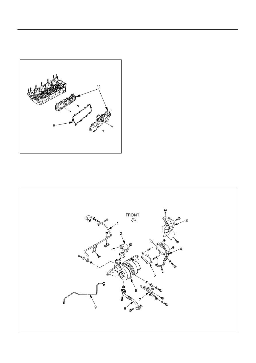
8. Gasket.
9. Injection pipe.
10. Intake manifold.
11. Gasket and discard.
Installation
1. Intake manifold.
Tighten:
Intake manifold to 19 N
⋅m(1.9 kg⋅m/ 14 lb⋅ft)
2. Injection pipe
Tighten:
Fuel injector line nuts to 26 N
⋅m(2.7 kg⋅m/ 20 lb⋅ft)
3. Gasket
4. Charge air pipe.
5. Engine harness connector.
6. Bracket engine stop cable and vacuum hose.
7. Bracket accelerator cable.
8. Connecting hose.
9. Accelerator cable injection pump side.
10. PCV hose.
Turbocharger
Refer to “Statement on Cleanliness and Care” previous-
ly in this section.
Component
N6A1375E
N6A1373E