Isuzu N-Series. Service manual - part 467


  Index      Isuzu     Isuzu N-Series - service and repair manual


Search            


Content   ..  465  466  467  468   ..


Isuzu N-Series. Service manual - part 467


6E-204 EMISSION AND ELECTRICAL DIAGNOSIS

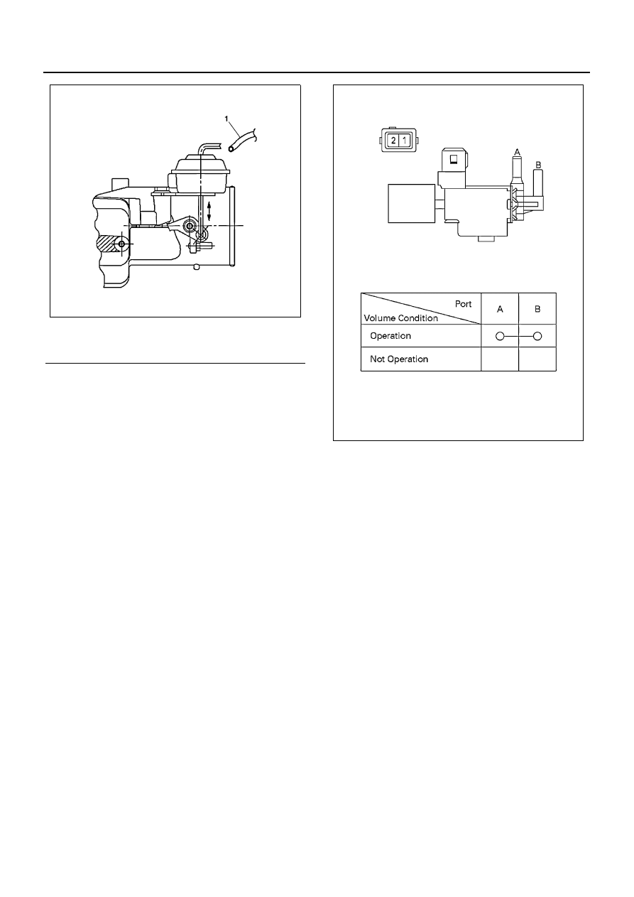
3. Intake Throttle Valve

Working Check

Disconnect the vacuum hose from the actuator and
try to move the rod by hand, making sure of the
smooth move of the rod.

4. EXHAUST GAS RECIRCULATION (EGR) SYS-

TEM MALFUNCTION4. Vacuum Switching Valve;
Intake Throttle

Inspection

Connect the vacuum switching valve connector
terminals No.1 and No.2 to (+) terminal and (-) ter-
minals of battery, respectively, and check the con-
tinuity between the ports.
If the check result is abnormal, repair or replace the
valve.

5. Accelerator Switch (2-pole connector type)

Inspection

1) Check the continuity between the switch con-

nector terminals.

Caution:
When measuring resistance with a circuit tester, be
careful not to damage or deform the terminals.

2) Check the smooth move of the pushrod. If the

check result is abnormal, repair or replace the
pushrod.

Legend

1. Vacuum hose

N6A1250E

N6A1251E

EMISSION AND ELECTRICAL DIAGNOSIS 6E-205

Removal

1) Accelerator Switch

Disconnect the connector.
Loosen the lock nut.
Turn the switch to remove.

Reinstallation

To install, follow the removal procedure in reverse
order:
1) Drive the threaded part of the switch until its

end surface becomes flush with that of the
bracket side of nut.

2) Tighten the lock nut.

Tighten:

• Lock nut to 1.3 N

⋅m (0.13 kg⋅m/11.5 lb⋅in)

N6A1252E

6E-206 EMISSION AND ELECTRICAL DIAGNOSIS

Exhaust Gas Recirculation (EGR) System Malfunction

N6A1680E

EMISSION AND ELECTRICAL DIAGNOSIS 6E-207

Inspection

1. Thermosensor (Engine coolant temperature)

Soak the temperature sensitive part of a ther-
mosensor in the water, and while changing the wa-
ter temperature, make sure the resistance is
changed as the following graph shows:

2. Vacuum Switching Valve (VSV)

Resistance Check

Check the resistance between the VSV connector
terminals using a circuit tester.
Cold Resistance
: 37 — 44 (

Ω) (for 12 volt model)

: 159 — 169 (

Ω) (for 24 volt model)

Connect battery voltage between VSV connector
terminals and make sure of the continuity between
the ports.

Airtight Check

Apply negative pressure to the negative pressure
input port as illustrated on the left.
Although there is leakage, it is no problem if the
negative pressure rises to -46.7 kPa (-350 mmHg /
-6.77 psi) or more.

Legend

1. Resistance (k

Ω)

2. ECT 

°F (°C)

N6A1254E

N6A1255E

Legend

1. 2 Pin
2. Port

N6A1264E

N6A1265E


Content   ..  465  466  467  468   ..