Isuzu N-Series. Service manual - part 423


  Index      Isuzu     Isuzu N-Series - service and repair manual


Search            


Content   ..  421  422  423  424   ..


Isuzu N-Series. Service manual - part 423


6E-28 EMISSION AND ELECTRICAL DIAGNOSIS
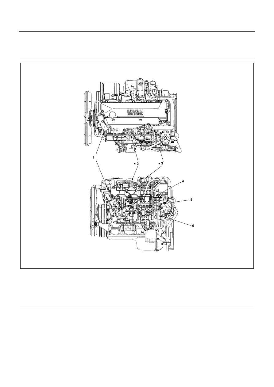
Legend

1. Data link connector (Left-hand drive)

3. Data link connector (Right-hand drive)

2. ECM including atmospheric

4. Intake air temp switch equipped with EGR and VSS

Legend

1. Engine coolant temperature sensor

5. Rock sensor

2. VSS

6. Engine speed sensor

3. EGR

* Equipped with EGR and VSS

4. Timing advance solenoid switch

N6A1140E

EMISSION AND ELECTRICAL DIAGNOSIS 6E-29

Parts Location

N6A1668E

6E-30 EMISSION AND ELECTRICAL DIAGNOSIS

Engine Control Module (ECM)

Appearance of ECM

Legend

1. ECM

A. Detail of 30 pins connector

2. Name plate

B. Detail of 22 pins connector

N6A1142E

EMISSION AND ELECTRICAL DIAGNOSIS 6E-31

Chart of Engine Control Module (ECM) Input/Output

Equipped 

without 

EGR and 

VSS

Equipped with EGR and 

VSS

Connector

Connector 

number

Connector name

4HE1-XS

4HE1-XN

4HE1-XS

Connec-
tor 30 pin

1

Checker SIG (Serial Communication)

2

Intake Temperature Switch

3

Engine Type

4

Not be used

5

Transmission Type

6

Rack Sensor (+5V)

7

Rack Sensor SIG

8

Battery (+)

9

Ignition Key

10

Not be used

11

Timing Advance Solenoid Switch Relay

12

Not be used

13

Electric Vacuum Regulating Valve Power 
Supply

×

14

Electric Vacuum Regulating Valve GND

×

15

Checker GND

16

Diag Control

17

Not be used

18

Not be used

19

Not be used

20

Not be used

21

Rack Sensor GND

22

ECM GND

23

Not be used

24

Not be used

25

Not be used

26

Not be used

27

Transmission Position Switch

28

Not be used

29

Not be used

30

FICD Magnetic Valve Power Supply


Content   ..  421  422  423  424   ..