Isuzu N-Series. Service manual - part 387


  Index      Isuzu     Isuzu N-Series - service and repair manual


Search            


Content   ..  385  386  387  388   ..


Isuzu N-Series. Service manual - part 387


6C-26 FUEL SYSTEM

Caution:

• Secure the dial gauge so that a stroke of 2 mm

(0.08 in) can be measured.

• Do not over-tighten the nut as the dial gauge shaft

may jam. (Confirm from the dial gauge that the
shaft moves smoothly.)

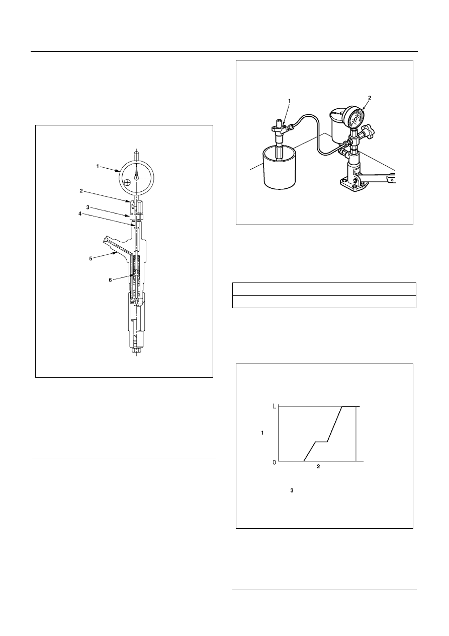
6. Set the nozzle holder (1) to the nozzle tester (2)

and put needle to zero on the dial gauge.

7. Operate the nozzle tester to bleed any air from in-

side the retaining nut and to confirm that no fuel
leaks.

8. Operate the nozzle tester and increase the in-line

pressure to 34.3 — 44.1 MPa (350 — 450 kg/cm

2

/ 4,975 — 6,396 psi) so that the nozzle’s needle
valve moves through its full lift.
Record full lift ‘L’. (Read dial gauge)

Notice:
The above operation is used to determine whether the
nozzle seat is worn and whether the nozzle assembly is
in good condition.

Legend

1. Dial gauge
2. Nut
3. Holder
4. Pin
5. Nozzle holder
6. First spring seat

N6A0873E

Nozzle Full Lift

mm (in)

0.30 (0.0118)

Legend

1. Needle valve
2. First nozzle opening pressure 34.3 — 44.1 

MPa (350 — 450 kg/cm

2

 / 4,975 — 6,396 psi)

3. In line pressure

N6A0867E

N6A0875E

FUEL SYSTEM 6C-27

Pre-lift Confirmation

1. With the needle valve at full lift, release the nozzle

tester handle.

Notice:
The in-line pressure will decrease and needle valve lift
(as indicated on the dial gauge) will also decrease a lit-
tle.

2. Read the needle valve lift ‘l’ from the dial gauge in-

dication (once the needle valve has descended
when the second spring has stopped operating).
Refer to the pre-lift measuring point for ‘l’.

Pre-lift measuring point:

Read the dial gauge at first nozzle opening pressure
+approx 1 MPa (10 kg/cm

2

 / 145 psi).

Notice:
This point can be found while the pressure is decreas-
ing.

3. Confirm that pre-lift ‘l’ is as specified.

Legend

1. Pressure gauge

Legend

1. Needle valve lift
2. In line pressure

N6A0876E

N6A1650E

Pre-lift

Engine

Pressure MPa (kg/cm

psi)

Lift mm (in)

4HG1-T

19.1 (195/2,770)

0.04 (0.0016)

Legend

1. Needle valve lift
2. Measuring point of prelift
3. First nozzle opening pressure

N6A0878E

N6A0879E

6C-28 FUEL SYSTEM

4. If pre-lift is not as specified, replace the pins, lift

piece, spacer and nozzle assembly as a set with
the service kit.

Second Nozzle Opening Pressure Confirmation

1. After pre-lift confirmation, operate the nozzle tester

to increase in-line pressure to 34.3 — 44.1 MPa
(350 — 450 kg/cm

2

 / 4,975 — 6,396 psi) so that the

nozzle’s needle valve moves through its full lift.

2. Release the nozzle tester handle so that in-line

pressure decreases.

Notice:
The in-line pressure will decrease and needle valve lift
(as indicated on the dial gauge) will also decrease a lit-
tle.

3. Then, read the pressure gauge indication (second

nozzle opening pressure) the instant that the dial

Legend

1. Push rod
2. Spring seat
3. Spacer
4. Second spring
5. Adjusting shim
6. Lift piece
7. Needle valve

Service kit:

4HG1-T

897313-8970

Legend

1. Lift piece
2. Nozzle assembly
3. Pin
4. Spacer
5. Capsule

N6A0880E

Legend

1. Nozzle holder
2. Nozzle tester

Legend

1. Needle valve lift
2. Second nozzle opening pressure 34.3 — 44.1 

MPa (350 — 450 kg/cm

2

 / 4,975 — 6,396 psi)

3. In line pressure

N6A0867E

N6A1651E

FUEL SYSTEM 6C-29

gauge indicates the specified needle valve lift (usu-
ally pre-lift l + 0.05 mm (0.0020 in).

Second Nozzle Opening Pressure Adjustment
If the second nozzle opening pressure is not as speci-
fied, disassemble the nozzle from the nozzle holder and
replace the shim until the pressure is as specified.

Caution:

• Because the second opening pressure changes

when the first opening pressure changes, the sec-
ond opening pressure must be adjusted when the
first opening pressure changes.

• Use a micrometer to measure shim thickness.

• Use some combination of 3 adjusting shims to ad-

just the pressure.

• Second nozzle opening pressure adjusting shims

Second Nozzle Opening Pressure

Lift mm (in)

Pressure MPa (kg/cm

2

/psi)

4HG1-T

0.09 

(0.0035)

22.1 — 23.0 (225 — 235/

3,200 — 3,342)

Legend

1. When needle valve lift is l + 0.05 mm (0.0020 

in)

2. Dial gauge
3. Full needle valve lift

Part No. (ISUZU)

Thickness mm (in)

897116-0290

0.10 (0.0039)

897116-0320

0.20 (0.0079)

897116-0330

0.30 (0.0118)

897116-0340

0.40 (0.0157)

897116-0350

0.50 (0.0197)

897116-0360

0.51 (0.0201)

N6A0883E

897116-0370

0.52 (0.0205)

897116-0380

0.53 (0.0209)

897116-0390

0.54 (0.0213)

897116-0400

0.55 (0.0217)

897116-0410

0.56 (0.0220)

897116-0420

0.57 (0.0224)

897116-0430

0.58 (0.0228)

897116-0440

0.59 (0.0232)

Legend

1. Second nozzle opening pressure adjusting 

shim

2. Second spring
3. Collar
4. Push rod
5. Spring seat

Part No. (ISUZU)

Thickness mm (in)

N6A0862E

N6A1652E


Content   ..  385  386  387  388   ..