Isuzu N-Series. Service manual - part 376


  Index      Isuzu     Isuzu N-Series - service and repair manual


Search            


Content   ..  374  375  376  377   ..


Isuzu N-Series. Service manual - part 376


6A3-156 ENGINE (4HF1 / 4HF1-2 / 4HE1-TC / 4HG1 / 4HG1-T)
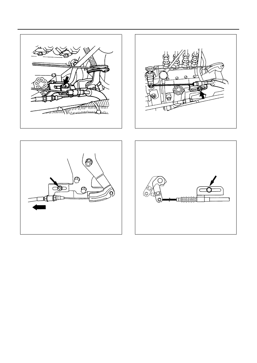
For 4HE1-TC

4) Check to see if the control lever of the injection

pump is at the idle position (with the lever in
touch with the stopper bolt).

4. Engine Stop Cable

1) Attach the end tip of the cable to the engine

stopper lever.

2) Pull the cable toward the rear side of the vehi-

cle, and fasten the clamp with a nut at the posi-
tion where the lever stops.

For 4HE1-TC

5. Vacuum Hose
6. Heater Hose

Install the hose with its mark (1) turned up.

N6A0526E

N6A0527E

N6A0525E

N6A0529E

ENGINE (4HF1 / 4HF1-2 / 4HE1-TC / 4HG1 / 4HG1-T) 6A3-157

7. Intake Air Duct

Transmission Side

1. Transmission Assembly

Fasten the transmission to the transmission jack
with a chain in the same manner as when dis-
mounting it, and tighten the clutch housing clamp-
ing bolt to the specified torque.
(Refer to the illustration below.)

2. Transmission Mounting Nut

Tighten:
Transmission mounting nut to 40 N

⋅m (4.1 kg⋅m/30 lb⋅ft)

3. Starter
4. Starter Earth Cable

Refer to the preceding page.

5. Clutch Slave Cylinder

1) Install the clutch slave cylinder.

Tighten:
Slave cylinder bolts to 16 N

⋅m (1.6 kg⋅m/12 lb⋅ft)

2) Install the clutch return spring to the clutch shift

fork.

6. Select Cable
7. Shift Cable
8. Parking Brake Cable

1) With the lock nut (1) of the parking brake side

cable tightened to the limit, rotate the nut (2) to
connect it with the front side cable.

2) After tightening the front side nut (2) to the limit,

fasten the parking brake cable with the lock nut
(1).

N6A0784E

N6A0787E

6A3-158 ENGINE (4HF1 / 4HF1-2 / 4HE1-TC / 4HG1 / 4HG1-T)

3) Pull the parking brake lever to the limit (with the

operating force of about 147 N (15 kg/33 lb) at
the hand), adjust the lever with the lever adjust-
ing nut so that the number of notches becomes
6 to 8 notches.

9. Harness Connector

10. Back-up Lamp Connector
11. Neutral Switch Connector
12. Car Speed Sensor Connector
13. Propeller Shaft Assembly

Tighten:
Propeller shaft bolt to 103 N

⋅m (10.5 kg⋅m/76 lb⋅ft)

Engine Warm-Up
After completing the required maintenance procedures,
start the engine and allow it to warm up. Then check the
following:

1) Engine idling speed

Refer to “Servicing” for the idling speed adjust-
ment procedure.

2) Engine noise level
3) Engine oil, coolant and fuel leakage
4) Engine control cable operation
5) Clutch engagement
6) Indicator warning light operation

N6A0786E

ENGINE COOLING 6B-1

ENGINE 4H SERIES

SECTION 6B

ENGINE COOLING

Contents

GENERAL DESCRIPTION ................................... 6B-2

Water Pump....................................................... 6B-3
Thermostat ........................................................ 6B-3
Radiator ............................................................. 6B-4
Anti-freeze Solution ........................................... 6B-4

WATER PUMP...................................................... 6B-6

Component ........................................................ 6B-6
Removal ............................................................ 6B-6
Inspection .......................................................... 6B-7
Installation ......................................................... 6B-7

THERMOSTAT ..................................................... 6B-9

Component ........................................................ 6B-9
Removal ............................................................ 6B-9
Inspection .......................................................... 6B-9
Installation ....................................................... 6B-10

RADIATOR.......................................................... 6B-11

Component ...................................................... 6B-11
Removal .......................................................... 6B-11
Inspection ........................................................ 6B-12
Installation ....................................................... 6B-12

DRIVE BELT ADJUSTMENT .............................. 6B-14

Component ...................................................... 6B-14
Inspection ........................................................ 6B-14


Content   ..  374  375  376  377   ..