Isuzu N-Series. Service manual - part 356


  Index      Isuzu     Isuzu N-Series - service and repair manual


Search            


Content   ..  354  355  356  357   ..


Isuzu N-Series. Service manual - part 356


6A3-76 ENGINE (4HF1 / 4HF1-2 / 4HE1-TC / 4HG1 / 4HG1-T)

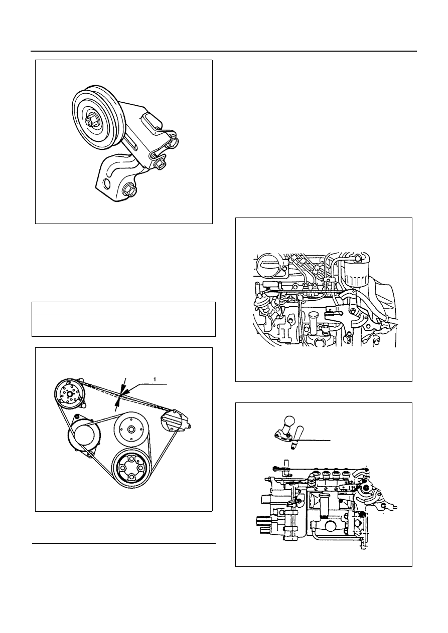
8. Air Conditioning (A/C) Drive Belt (If equipped with

A/C)

• Install drive belt adjust belt tension by adjusting

bolt and tighten locking nut to the specified
torque.

• Depress the drive belt mid-portion with a 98 N

(10 kg/22 lb) force.

Tighten:
Locking nut to 27 N

⋅m (2.8 kg⋅m/20 lb⋅ft)

9. Injection Pump Rubber Spacer (4HF1/4HG1-T)

10. Injection Pump Assembly

11. Injection Pipe
12. Water Bypass Hose
13. Positive Crankcase Ventilation (PCV) Hose
14. Fuel Pipe
15. Leak Off Pipe
16. Nozzle Cover
17. Fuel Feed Hose
18. Fuel Return Hose
Air Bleeding
Above works refer to “INJECTION PUMP ASSEMBLY”
section in this manual.
19. Oil Pipe
20. Engine Control Lever Assembly

Tighten:
Engine control lever bolt to 24 N

⋅m (2.4 kg⋅m/17 lb⋅ft)

21. Engine Control Cable

22. Accelerator Control Cable

1) Check to see if the idling control knob is turned

to the utmost limit to the left.

Drive Belt Deflection

mm (in)

16 — 20 (0.63 — 0.79) ... New belt

18 — 22 (0.71 — 0.87) ... Reuse belt

Legend

1. Belt deflection

N6A0289E

N6A0418E

N6A0449E

N6A0544E

ENGINE (4HF1 / 4HF1-2 / 4HE1-TC / 4HG1 / 4HG1-T) 6A3-77

2) Install the end tip of the cable to the engine con-

trol lever.

3) With the outer cable pulled toward the front of

the vehicle, provide the engine control wire and
the inner cable with the appropriate play. Then,
fasten the clamp with a nut.

For 4HE1-TC

4) Check to see if the control lever of the injection

pump is set at the idling position (with the lever
attached to the stopper bolt).

23. Engine Stop Cable

1) Install the end tip of the cable to the engine stop

lever.

2) Pull the cable toward the rear of the vehicle,

and fasten the clamp with a nut at the position
where the lever stops.

For 4HE1-TC

24. Intake Air Duct
25. Oil Level Gauge Guide Tube

1) Install the O-rings to the guide tube lower por-

tion and insert the guide tube completely to the
cylinder body.

2) Tighten the guide tube bolt to the specified

torque.

Tighten:
Guide tube bolt to 13 N

⋅m (1.3 kg⋅m/113 lb⋅in)

N6A0526E

N6A0527E

N6A0525E

N6A0529E

6A3-78 ENGINE (4HF1 / 4HF1-2 / 4HE1-TC / 4HG1 / 4HG1-T)

26. Vacuum Hose

• Pour coolant into radiator.
• Connect battery ground cable.
• Start engine and check for oil and water leak-

age carefully.

N6A0390E

ENGINE (4HF1 / 4HF1-2 / 4HE1-TC / 4HG1 / 4HG1-T) 6A3-79

OIL PAN

Component

Removal

Preparation

• Disconnect battery ground cable
• Lift up car
• Drain engine oil

1. Spacer Rubber

• Remove the stiffener before removing the

spacer rubber.

2. Oil Pan

Installation

1. Oil Pan

1) Apply a 3 mm (0.12 in) bead of recommended

liquid gasket (Three Bond 1207C) or its equiv-
alent to the shaded areas shown in the illustra-
tion.

Legend

1. Spacer rubber

3. Gasket

2. Oil pan

4. Rubber assembly

N6A0550E

N6A0551E


Content   ..  354  355  356  357   ..