Isuzu N-Series. Service manual - part 339


  Index      Isuzu     Isuzu N-Series - service and repair manual


Search            


Content   ..  337  338  339  340   ..


Isuzu N-Series. Service manual - part 339


6A3-8 ENGINE (4HF1 / 4HF1-2 / 4HE1-TC / 4HG1 / 4HG1-T)

tributes to increased power output and fuel
efficiency (See figure).

• The rocker shaft is chrome plated to secure suffi-

cient durability.

Fuel System

LINE Pump

• The injection pump is of Bosch A type with the

plunger outside diameter of 9.5 mm (0.37 in) and
cam lift of 9 mm (0.35 in).
The plunger has a special notch for advancing the
timing at starting.

• The governor is of a mechanical RLD type to en-

sure sustained power at high speed.

• The timer is of the SCDM (eccentric) type. 

VE Pump

• A Bosch Distributor Type injection Pump is used. 

A single reciprocating / revolving plunger delivers
the fuel uniformly to the injection nozzles, regard-
less of the number of cylinders.

• The governor, the injection timer, and the feed

pump are all contained in the injection pump hous-
ing. The injection pump is compact, light weight,
and provides reliable high-speed operation. 

An android compensator is available as an option
for vehicles to be operated at high altitudes. It ad-
justs the fuel and air mixing ratio.
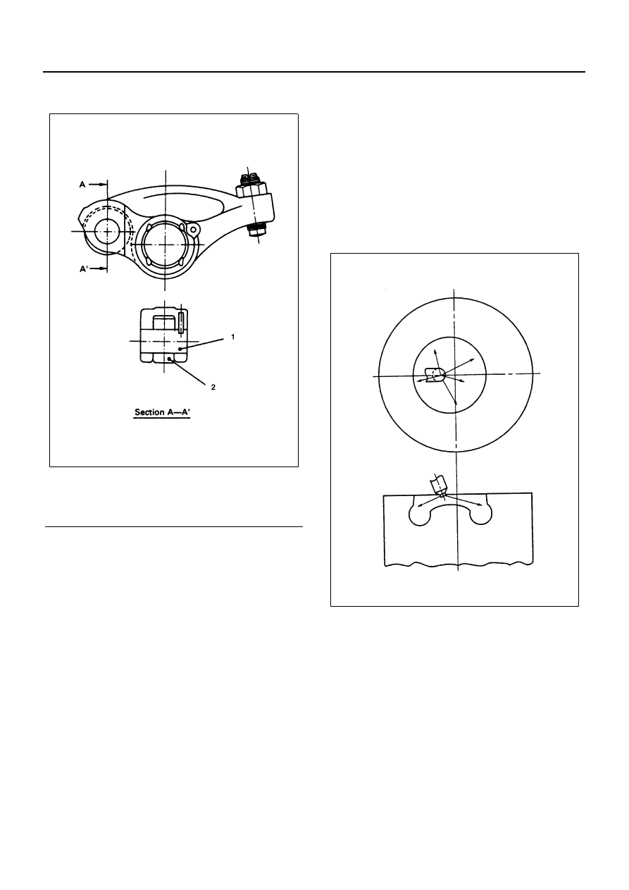
Injection Nozzle

• The injection nozzle is of the P type to bring it as

technically close as possible to the center of the
combustion chamber. The nozzle inclination is also
reduced to minimum to increase combustion effi-
ciency. 
The nozzle has five jets and the valve opening
pressure is set at 185 kg/cm

2

 (2,630 psi, 18,142

kPa) (See figure).

• The injection pipe is laid in such a way that the

overall length is minimized to enhance perfor-
mance.

Intake and Exhaust Systems

• The resin-made intake manifold is of the cover type

having an inner cover made of rubber and steel.
This design effectively reduces radiant sound and
transmitted sound.

• The intake manifold has a straightening vane in-

side to stabilize swirl and improve performance. It
also contains a built-in Positive Crankcase Ventila-
tion (PCV) valve to minimize the overall size (See
figure).

• The exhaust manifold is mode of cast iron and he-

atresisting alloys. Ports are shaped carefully to
minimize exhaust resistance.

Legend

1. Pin
2. Roller

N6A0374E

N6A0375E

ENGINE (4HF1 / 4HF1-2 / 4HE1-TC / 4HG1 / 4HG1-T) 6A3-9

Lubrication System

• The oil pump is driven by the crank gear directly to

increase durability while maintaining sufficient de-
livery. 
The pump body is partially integrated with the cyl-
inder block to reduce the overall size and weight
(See figure)

• The oil filter is of the cartridge type integrating the

full flow filter and bypass filter as a single unit. This
presents several advantages such as an extended
interval between oil exchanges and greater ease of
maintenance resulting in cost reduction. The by-
pass valve is fitted to the body itself to avoid flow of
foreign matter due to bypassing of oil thereby
maintaining sufficient reliability.

• The oil cooler is of a large-capacity, water-cooled

and multiple-partition type built into the side of the
cylinder block. This design maintains necessary
stability in oil temperature. It also has a bypass
valve to minimize delay of the oil gallery pressure
build-up for cold starting.

Cooling System

• The water pump is driven by a V-belt and the pump

body is made of diecast aluminum. Part of the swirl
chamber is built into the engine front cover to re-
duce the overall size and weight.
A sintered carbon type seal unit is chosen to se-
cure reliability. The shaft bearing combines roller
bearing and ball bearing to maintain necessary du-
rability. The outlet for draining is located behind the
pulley to prevent dust from entering the system as
much as possible. (See figure)

• The cooling fan operation is regulated by a temper-

ature-sensitive clutch to enhance fuel efficiency
while reducing noise.

Legend

1. Straightening wall

N6A0376E

Legend

1. Oil pump gear

N6A0377E

6A3-10 ENGINE (4HF1 / 4HF1-2 / 4HE1-TC / 4HG1 / 4HG1-T)

Important Operations

1. Axial Type Oil Seal

• As crankshaft front and rear oil seals are both axial type, attention must be paid to the following:

when replacing, replace oil seal and slinger as a set.

• Be sure to use the special tool correctly since oil seal and slinger must be set accurately in their longitudinal

direction.

2. Valve Cap

• As intake and exhaust valves have caps, take sufficient care not to let them fall into the gear case or oil return

hole during disassembly or reassembly.

3. Application of Liquid Gasket

• Oil pan, crankcase, oil cooler, retainer front, and water pump are not sealed with sheet gasket but with liquid

gasket only.

• Prior to application, be sure to remove old hardened liquid gasket or oil from those surfaces to which new

gasket will be applied. Further, if the old gasket can hardly be removed, mask such surfaces with gasket re-
mover (Three Bond PANDO-391D; ISUZU Genuine Parts No. 1-8844-0542-0) or equivalent in accordance
with the instructions manual.

• Liquid gasket should be applied evenly so that no breaks and omissions may be made. Further, were O-ring

is used should not be exposed to liquid gasket.

4. Plastic-Region Angular Bolt Tightening Method

• Clamping bolts of connecting rod and cylinder head (M14 only) are tightened by plastic region angular bolt

tightening method. This method is applied with bolt threads and setting faces coated with molybdenum
disulfide grease.

N6A0378E

Legend

1. Fan center
2. Fan pulley
3. Seal unit
4. Roller bearing
5. Ball bearing
6. Impeller

ENGINE (4HF1 / 4HF1-2 / 4HE1-TC / 4HG1 / 4HG1-T) 6A3-11

ENGINE MOUNT (RH,LH)

Component

Removal

Preparation

• Disconnect battery ground cable.
• Tilt the cab.

1. Transmission Panel
2. Fan Guide

Remove the fan guide and hang it on the fan side.

3. Engine Mount

1) Hang the engine by the hoist before dismount-

ing the engine mount.

2) Remove the nuts that fix the engine foot and

the engine mount.

3) Remove the fixing bolts on the chassis frame

side of the engine mount.

4) Hoist the engine assembly a little, and dis-

mount the engine mount.

Legend

1. Transmission panel

3. Engine mount

2. Fan guide

N6A0379E

N6A0380E


Content   ..  337  338  339  340   ..