Isuzu N-Series. Service manual - part 336


  Index      Isuzu     Isuzu N-Series - service and repair manual


Search            


Content   ..  334  335  336  337   ..


Isuzu N-Series. Service manual - part 336


6A-86 ENGINE MECHANICAL

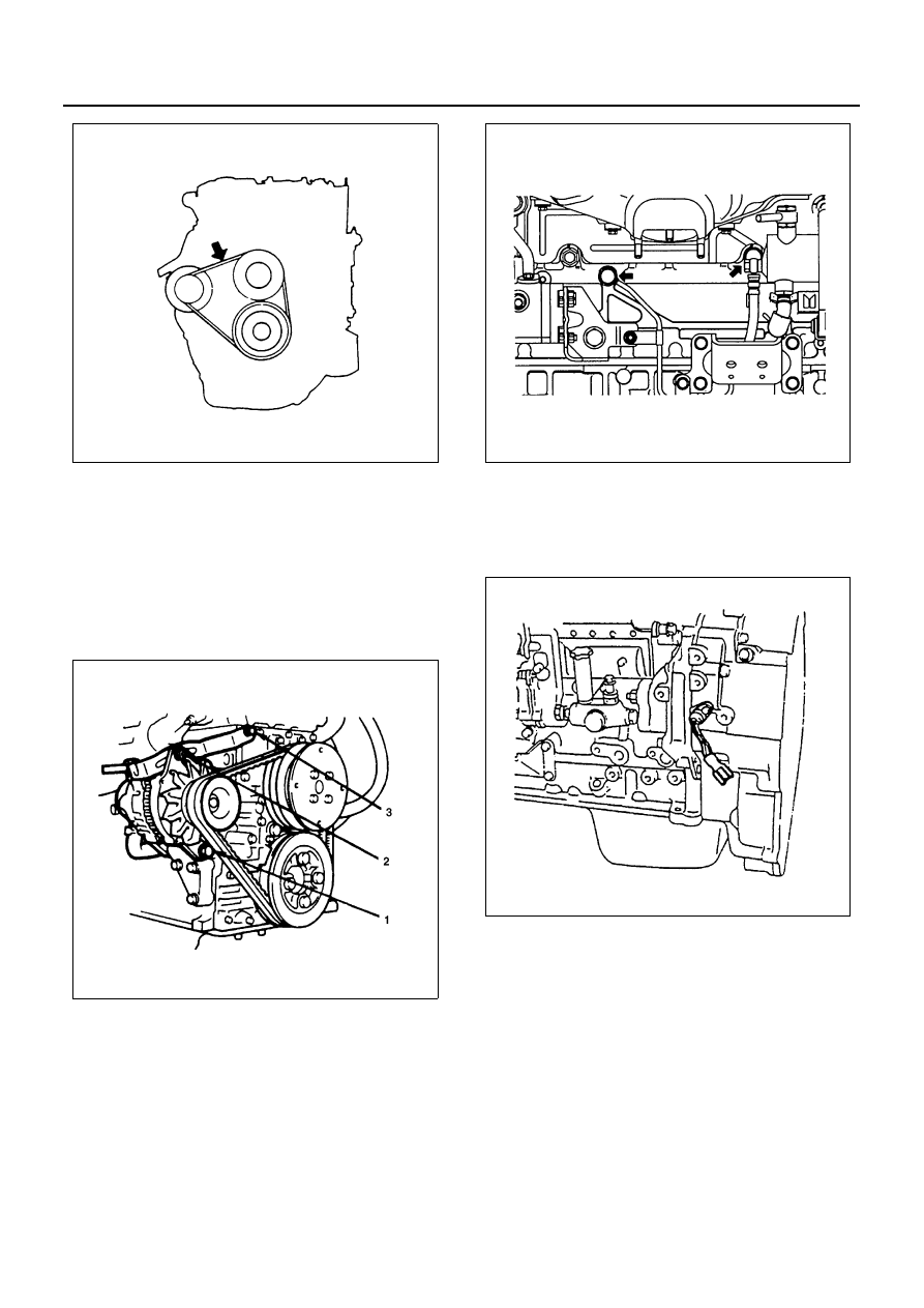
47. Fan Belt Adjustment

Fan belt tension is adjusted by moving the alterna-
tor.

Tighten:
Bolt to

• (1): 40 N

⋅m (4.1 kg⋅m / 30 lb⋅ft)

• (2): 24 N

⋅m (2.4 kg⋅m / 17 lb⋅ft)

• (3): 46 N

⋅m (4.7 kg⋅m / 34 lb⋅ft)

48. Vacuum Pump Rubber Hose
49. Vacuum Pump Oil Pipe

Tighten:
Cylinder body side pipe to 41 N

⋅m (4.2 kg⋅m / 30 lb⋅ft)

Tighten:
Generator side pipe to 23 N

⋅m (2.3 kg⋅m / 17 lb⋅ft)

50. Fuel Pipe Bracket
51. Tachometer Sensor

Tighten:
Tachometer bolt to 8 N

⋅m (0.8 kg⋅m / 6 lb⋅ft)

52. Oil Filter Assembly

Tighten:
Oil filter bolt to 48 N

⋅m (4.9 kg⋅m / 35 lb⋅ft)

53. Oil Pipe

Tighten:
Oil pipe joint bolt to 17 N

⋅m (1.7 kg⋅m / 12 lb⋅ft)

N6A0037E

N6A0038E

N6A0347E

N6A0348E

ENGINE MECHANICAL 6A-87

54. Engine Control Lever Assembly

Tighten:
Engine control lever bolt to 24 N

⋅m (2.4 kg⋅m / 17 lb⋅ft)

55. Engine Control Wire

56. Driven Plate

Use the clutch pilot aligner to install the driven
plate.
Clutch Pilot Aligner: 5-8840-2240-0

57. Clutch Pressure Plate Assembly

1) Align the clutch pressure plate with the flywheel

knock pin.

2) Tighten the pressure plate bolts to the specified

torque in numerical order.

Tighten:
Clutch pressure plate bolt to 40 N

⋅m (4.1 kg⋅m / 30 lb⋅ft)

58. Cylinder Head Gasket

N6A0285E

N6A0350E

Legend

1. Clutch pilot aligner
2. Clutch pressure plate assembly
3. Driven plate

Legend

A. Knock pin

N6A0351E

N6A0282E

6A-88 ENGINE MECHANICAL

1) When any of the cylinder block, crankshaft,

crankshaft bearing, connecting rod, connecting
rod bearing, and piston is replaced with a new
one, cylinder head gasket thickness should be
determined newly.

2) When replacing the cylinder head gasket alone

without replacing any of the parts mentioned in
1) above, the gasket to be used should be the
same grade as the one used before.

3) Correct the cylinder head gasket thickness is

important. Installing the wrong thickness gas-
ket can result in greatly reduced engine perfor-
mance.

4) There are three cylinder head gaskets avail-

able.

59. Piston Head Projection Measurement

• Select a cylinder head gasket.
• Clean thoroughly the top faces of the piston head

and the cylinder body.

• Use the dial gauge to measure the piston head pro-

jection. Take measurements at two locations for
each cylinder.

• The measurement points of the piston head and

the reference point of the cylinder body are shown
in the illustration.
Measurement points: Points G1 and G2 of the pis-
ton head
Reference point: Point R on the top face of the cyl-
inder body

Notice:
Note that there are three types of a cylinder head gasket
available as shown in the table following, according to
the piston projection.

• For each cylinder, calculate the average value (Ti)

of the piston projection.

• Find the maximum value (Timax) of the average

value (Ti) of each cylinder.

• Based on the Timax obtained, select a gasket of

the appropriate grade.

4HF1/4HF1-2/4HG1-T
Cylinder Head Gasket Selection

N6A0353E

N6A1628E

N6A1396E

ENGINE MECHANICAL 6A-89

4HE1-TC
Cylinder Head Gasket Selection

• Apply a 3 mm (0.12 in) bead or recommended liq-

uid gasket or its equivalent to the shaded areas
shown in the illustration.

• Install the cylinder head gasket with its “PART

NUMBER” mark facing up and toward the left of the
engine.

Caution:
Do not reuse the cylinder head gasket.

60. Cylinder Head Assembly

Above works refer to “CYLINDER HEAD” section
6A3 in this manual.

N6A1397E

N6A0353E

Legend

1. Bead width 

φ3

N6A0356E

N6A0105E


Content   ..  334  335  336  337   ..