Isuzu N-Series. Service manual - part 295


  Index      Isuzu     Isuzu N-Series - service and repair manual


Search            


Content   ..  293  294  295  296   ..


Isuzu N-Series. Service manual - part 295


HSA (HILL START AID) 5A5-59
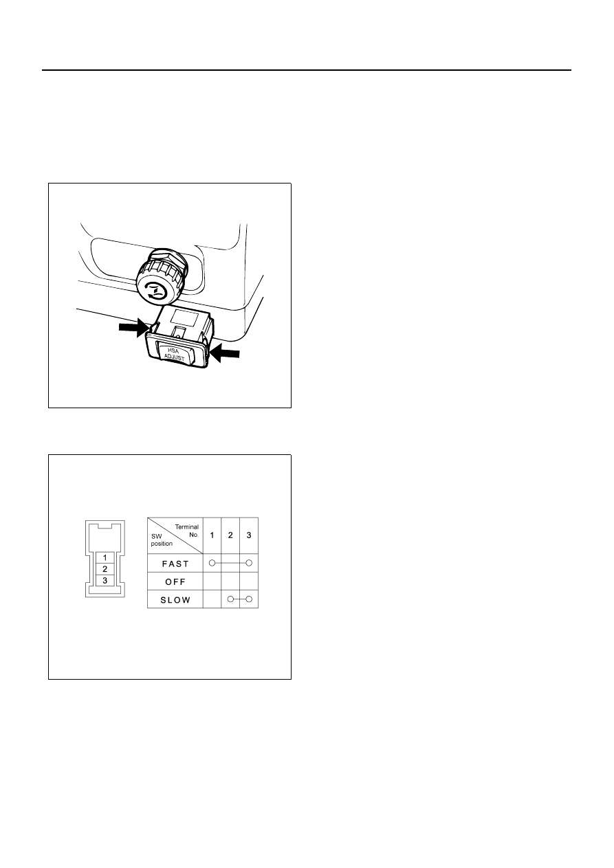
HSA Adjust Switch

Removal

1. Disconnect the connector.
2. Remove the HSA adjust switch.

• Remove it while pressing the switch claw from

the backside of the instrument panel.

Inspection

Check for continuity between the switch terminals.

Installation

Install in the reverse order of removal.

N5A3047E

N5A3048E

5A5-60 HSA (HILL START AID)

Speed Sensor

Removal

1. Remove the protector.
2. Disconnect the connection of the connector.
3. Remove the speed sensor.

Legend

1. Protector
2. Connector
3. Speed sensor

Inspection

1. Connect a resistance of 390

Ω±5%, 2W between

the speed sensor connector terminal 1 “J-32” and
the battery (+) terminal, and connect 2 “J-32” to the
battery (

−) terminal.

Caution:

Never connect the battery (+) terminal to the connector
3 “J-32”. It may cause the speed sensor failure.

2. Measure the voltage between 3 “J-32” and 2 “J-32”

using a digital tester while slowly rotating the speed
sensor shaft.
The voltage shows 2V

±1V and 14V (+1V, −2V) re-

peatedly for 8 times per one rotation of the shaft.
If the result of the inspection is unsatisfactory, re-
place with a new part.

Installation

1. Install the speed sensor.

Tighten:

Speed sensor to 25 N

⋅m (2.5 kg⋅m/18.4 lb⋅ft)

2. Install the protector.
3. Connect the connector.

N5A3049E

N5A3050E

HSA (HILL START AID) 5A5-61

Door Switch

Removal

1. Remove the installing screw while pressing the

sliding part of the door switch.

• Disconnect the connector.

Legend

1. Sliding part
2. Screw

Inspection

Move the sliding part to check for continuity between the
terminal and the body.

Installation

Install in the reverse order of removal.

N5A3051E

N5A3052E

5A5-62 HSA (HILL START AID)

Parking Brake Switch

Removal

1. Remove the parking brake rear cover.

• Disconnect the two clips.

2. Remove the parking brake switch.

• Remove the one installing screw.
• Disconnect the connector.

Inspection

1. Disconnect the parking brake switch connector.
2. Connect the circuit between the switch terminal

and the body to check for continuity.
With parking brake applied = Continuity exists
With parking brake released = No continuity
If the result of the inspection is unsatisfactory, re-
pair or replace with a new part.

Legend

1. Parking brake lever
2. Parking brake switch

Installation

Install in the reverse order of removal.

N5A3053E

N5A3054E


Content   ..  293  294  295  296   ..