Isuzu N-Series. Service manual - part 275


  Index      Isuzu     Isuzu N-Series - service and repair manual


Search            


Content   ..  273  274  275  276   ..


Isuzu N-Series. Service manual - part 275


5A4-74 ABS/ASR

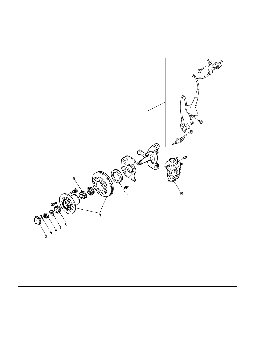
Speed Sensor (Front)

Components

Legend

1. Speed sensor (model with rigid suspension)
2. Hub cap
3. Cotter pin
4. Hub nut
5. Thrust washer

6. Outer bearing
7. Hub & rotor assembly
8. Inner bearing
9. Sensor rotor

10. Disc caliper assembly

Removal

1. Harness connector

• Disconnect the harness connector.

2. Harness fixing bolt

• Remove the harness fixing bolt.

3. Sensor fixing bolt

• Remove the sensor fixing bolt.

4. Speed sensor (front)

Installation

CAUTION:

• Do not let the speed sensor body contact with the

sensor rotor during hub assembly. Otherwise the
parts will be damaged.

• The speed sensor body has a built-in magnet. Be

careful not to allow metallic materials attached to it.

N5A2048E

ABS/ASR 5A4-75

• Remove the speed sensor before removing the

hub & rotor assembly or the hub & drum assembly.

• Remove the speed sensor before hammering to re-

move the knuckle etc.

• Use the harness line as a reference to avoid the

harness from twisting, when installing the sensor
harness.

• To install the sensor, press-fit the sensor until the

sensor flange contacts closely with the installing
surface by your hand, and then tighten with the
bolt.

1. Speed sensor (front)

• Install the speed sensor.

2. Sensor fixing bolt

• Install the sensor fixing bolt.

Tighten:

Bolt to 22 N

⋅m (2.2 kg⋅m / 16.2 lb⋅ft)

3. Harness fixing bolt

• Install the harness fixing bolt.

Frame side

Tighten:

Bolt to 22 N

⋅m (2.2 kg⋅m / 16.2 lb⋅ft)

Tighten together with the dust cover
(model with dram brake)

Tighten:

Bolt to 15 N

⋅m (1.5 kg⋅m / 11.1 lb⋅ft)

Tighten together with the brake support
(model with rigid disc brake)

Tighten:

Bolt to 45 N

⋅m (4.6 kg⋅m / 33.2 lb⋅ft)

4. Harness connector

• Connect the harness connector.

Inspection

This section explores inspection procedures as the ref-
erence to perform “Diagnostics with symptom” and “Di-
agnosis with illumination pattern”.

FL Wheel Speed Sensor Output Check Procedure
Check flow C-1-1

Without Tech 2

With Tech 2

Speed sensor output check

Check flow C-1-1 — C-1-4

Check flow TC-1

Step

Action

Value

YES

NO

1

1. Turn the starter switch OFF.
2. Disconnect the EHCU connector.
3. Jack-up the vehicle to lift the front wheels

off the floor.

4. Measure the AC voltage between the J-

177 connector terminals 32 and 33 while
turning the FL wheel half turn/sec.

Is the value within specified value?

200mV or 

more

Go to Step5

Go to Step2

2

1. Disconnect the FL sensor connector J-

75.

2. Measure the resistance between the J-75

connector terminals 1 and 2 (sensor
side).

Is the value within specified value?

1 — 2k

Go to Step4

Go to Step3

3

Replace the FL sensor.

Is this step completed?

Go to Step5

4

Repair the circuit for open/short circuit, and
the connector for improper connection
between the connector of EHCU and the sen-
sor connector.

Is this step completed?

Go to Step5

5A4-76 ABS/ASR

FR Wheel Speed Sensor Output Check Procedure
Check flow C-1-2

Speed Sensor Output Check Procedure (With Tech 2)
Check flow TC-1

5

1. Install all the components, and check that

those are installed properly.

2. Clear the DTC.

Is this step completed?

Go to “Diagnostic 

basic flow”.

Go to Step5

Step

Action

Value

YES

NO

1

1. Turn the starter switch OFF.
2. Disconnect the EHCU connector.
3. Jack-up the vehicle to lift the front wheels

off the floor.

4. Measure the AC voltage between the

J177 connector terminals 10 and 11 while
turning the FR wheel half turn/sec.

Is the value within specified value?

200mV or 

more

Go to Step5

Go to Step2

2

1. Disconnect the FR sensor connector J-

74.

2. Measure the resistance between the J-74

connector terminals 1 and 2 (sensor
side).

Is the value within specified value?

1 — 2k

Go to Step4

Go to Step3

3

Replace the FR sensor.

Is this step completed?

Go to Step5

4

Repair the circuit for open/short circuit, and
the connector for improper connection
between the connector of EHCU and the sen-
sor connector.

Is this step completed?

Go to Step5

5

1. Install all the components, and check that

those are installed properly.

2. Clear the DTC.

Is this step completed?

Go to “Diagnostic 

basic flow”.

Go to Step5

Step

Action

Value

YES

NO

1

1. Connect the Tech 2.
2. Check each sensor lowest speed from

the “Wheel sensor”.

 Is the sensor speed 4km/h (2mph) or more?

Go to Step2

Go to Step6

2

 Check the suspicious sensor circuit for open
circuit. (Check with shaking the wire and the
connector.)

 Is the sensor circuit connection normal?

Replace the 

speed sensor.Go 

to Step3

Repair.Go to 

Step3

Step

Action

Value

YES

NO

ABS/ASR 5A4-77

Used for checking the front speed sensor, or the rear
speed sensor when no DTC is set.

CAUTION:

On the vehicle that the rear tires have smaller diameter,
the rear wheel speed may be indicated a little higher
than the front wheel speed. Check the speed after driv-
ing a while at a constant speed.

3

Check each sensor lowest speed from the
“Wheel sensor”.

Is the sensor speed 4km/h (2mph) or more?

Go to Step4

Go to Step6

4

Check the sensor rotor.

Is the sensor rotor normal?

Go to Step5

Replace the sen-

sor rotor.Go to 

Step5

5

Check each sensor lowest speed from the
“Wheel sensor”.

Is the sensor speed 4km/h (2mph) or more?

Repair the circuit 

or circuit between 

the EHCU and the 

speed sensor. Go 

to Step6

Go to Step6

6

Install all the components, and check that
those are installed properly.

Is this step completed?

Repeat “Diagnos-

tic basic flow”.

Go to Step6

Step

Action

Value

YES

NO


Content   ..  273  274  275  276   ..